22
promesstec GmbH
I Niedersachsenstraße 4 I D-48465 Schüttorf I Tel.:+49 (0)5923/ 90 229 0 I Fax:+49 (0)5923/ 90 229 29
E-Mail: [email protected] I Internet: www.promesstec.com
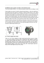
Installation of the separate evaluation unit of the flow meter
The version HEAD (85mm) - it is a remote evaluation electronics (according to order).
Firstly decide if you want to install the fixing bracket behind, or under the electronics
(the bracket with holes upward or downward). Install the fixing bracket on the meter's
aluminium housing; place the unit as required on the wall or on a structure and mark
the holes in this position for the attachment of the bracket. Unscrew the bracket and
attach it to the marked location, e.g. using wall plugs and screws. Screw down the
electronics on to the fixing bracket and connect the sensor cable using the connector.
Attach the cable to the wall or to the structure so that it does not "dangle" from the
connector. Make a "drip loop" downwards so that water cannot trickle onto the con-
nector. Fix the conductors for power and the outputs in a similar way. After installa-
tion of all cables, turn the electronics to the required position and fix the unit to the
bracket by tightening the fastening nut.
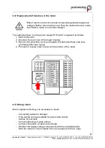
4.6 Power supply cover sheet
There is a cover sheet installed on power supply board with the access to jumper
J1. This jumper switches invoicing mode to operational. Basic difference between
the states with and without the jumper is in the level of control. The version with
installed jumper allows the user to adjust almost all parameters. On the contrary,
the version without jumper only controls parameters that do not have influence on
meteorological settings. If the sensor must comply with meteorological approval,
there will be metrological seal over the jumper.


