background image

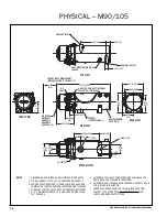
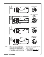
AIR INTAKE OPTION:

3" OD SNORKEL SEE NOTE 7

AIR INTAKE OPTION: 2.25" OD ELBOW

WITH 26° ADAPTER PLATE

SEE NOTE 7

CAN BE INSTALLED AT:

26°, 116°, 206°, 296°

AIR INTAKE OPTION:

2.25" OD SNORKEL SEE NOTE 7

AIR INTAKE OPTION: 2.25" OD

ELBOW SEE NOTE 7

CAN BE INSTALLED AT:

0°, 90°, 180°, 270°

28.31 (719

)

8.71

(221

)

SERVICE

SPACE

REQUIREMENT

(SEE NOTE 3)

9.21

(

234)

33.09 (840

)

7.93
(201

SERVICE

SPACE

REQUIREMENT

(SEE NOTE 3)

9.99

(

254)

28.00 (711

)

9.02

(22.9

)

SERVICE

SPACE

REQUIREMENT

(SEE NOTE 3)

8.90

(

226)

28.80 (732)

8.22

(209)

SERVICE

SPACE

REQUIREMENT

(SEE NOTE 3)

9.70 (246)

90°

270°

180°

116°

26°

296°

206°

1. DIMENSIONS ARE IN INCHES (MILLIMETERS IN BRACKETS).

2. TYPICAL EXHAUST CUTOUT 3.25" CENTERED ON EXHAUST.

3. SERVICE SPACE REQUIRED TO REMOVE BURNER HEAD AND

COMBUSTION TUBE FOR PERIODIC INSPECTION AND CLEANING.

4. THE EXHAUST PIPE SHOULD HAVE A MINIMUM DIAMETER OF

2.75", A MAXIMUM LENGTH OF 5' AND HAVE NO MORE THAN
180° OF BENDS.

5. ALTERNATE FUEL INLET CONFIGURATIONS AVAILABLE, SEE

PARTS BOOK FOR FURTHER INFORMATION.

6. ALTERNATE HEAT EXCHANGERS AVAILABLE, SEE PARTS BOOK

FOR FURTHER INFORMATION.

7. SNORKEL HOSE REQUIRED FOR THIS AIR INTAKE OPTION.

CONTACT TECH SUPPORT AT WWW.PROHEAT.COM FOR
LENGTH AND BEND RESTRICTIONS.

NOTES:

1-7

PROHEAT M-SERIES G-II PCM SERVICE MANUAL

Summary of Contents for M105 G-II PCM

Page 1: ...G II PCM SERVICE MANUAL M50 M80 90 M105 125 SERIAL NUMBERS G II PCM MODEL HEATERS 705000 TO DATE AND ALL MODELS EQUIPPED WITH A G II REPLACEMENT PCM Rev C ...

Page 2: ...gnostic Code 1 4 5 4 1 3 FLAME OUT Diagnostic Code 2 4 23 4 1 4 COOLANT FLOW Diagnostic Code3 4 24 4 1 5 OVERHEAT Diagnostic Code 4 4 25 4 1 6 VOLTAGE Diagnostic Code 5 4 26 4 1 7 FLAME FAULT Diagnostic Code 6 4 27 4 1 8 TEMP SENSOR COOLANT FLOW Diagnostic Code 7 4 27 4 1 9 FUEL SOLENOID VALVE Diagnostic Code 8 4 29 4 1 10 NOT USED Diagnostic Code 9 4 29 4 1 11 IGNITION MODULE Diagnostic Code 10 4...

Page 3: ... 4 Air Compressor 4 36 4 2 5 Fuel Supply Pump 4 36 4 2 6 Ignition Electrodes 4 36 4 2 7 G II PCM Fuse 4 36 4 3 OPERATIONAL PROBLEMS 4 36 5 0 MAINTENANCE 5 1 5 1 WEEKLY MAINTENANCE 5 1 5 2 ANNUAL MAINTENANCE 5 2 5 3 ROTARY VANE COMPRESSOR SERVICE VANES INSTALLATION 5 7 6 0 PROHEAT WARRANTY 6 1 ii PROHEAT M SERIES G II PCM SERVICE MANUAL ...

Page 4: ...azards Strict compliance with these special instructions and common sense are major accident prevention measures DANGER Immediate hazards that will result in severe injury or death WARNING Hazards or unsafe practices that could result in severe personal injury or death NOTICE Information that is important to proper installation or maintenance but is not hazard related CAUTION Hazards or unsafe pra...

Page 5: ... severe injury and or death Before working on any unit shut it off Do not operate any unit until protective covers have been replaced Always ensure bolts and clamps are correctly torqued and secured Inspect mechanical components periodically for damage and corrosion Coolant Never remove the filler cap when the engine is hot escaping steam or scalding water could cause serious personal injury The c...

Page 6: ...t engine running The PROHEAT can be used while the vehicle is operating to provide supplemental heat for the engine and or passenger compartment 3 Cargo Heat The PROHEAT can supply heat to individual compartments as a stand alone heating system or it can provide supplemental heat to an existing heating system 4 Marine Marine applications typically involve the engineering and installation of a comp...

Page 7: ...PROHEAT M SERIES G II PCM SERVICE MANUAL B 2 ...

Page 8: ...G II PCM Please see G I PCM Service Manual M50 M80 part number SL9150 This can be found by visiting www proheat com Figure C 1 G I PCM and G II PCM G I PCM G II PCM METRI PACK 12052644 AUX CONNECTOR KEYING 7 PIN DATA LINK CONNECTOR FOUR PIN DUAL MODE TEMPERATURE SENSOR CONNECTOR METRI PACK 12052641 AUX CONNECTOR KEYING 2 X TWO PIN ANALOG TEMPERATURE SENSOR CONNECTORS 6 PIN DATA LINK CONNECTOR NO A...

Page 9: ...NO STATUS INDICATOR LIGHT ANALOG SENSOR HAS 2 PIN CONNECTOR G I PCM ANALOG TEMP SENSOR Figure C 2 G II PCM can be identified on a heater by looking for the status indicator light Also the Dual Mode Temp Sensor has a 4 pin connector Figure C 3 G I PCM can be identified on a heater by not having the status indicator light Also the Analog Temp Sensor has a 2 pin connector ...

Page 10: ...has been replaced with the diaphragm type Both styles can be identified in the Figures below Please refer to the M Series Parts Book at www proheat com for part numbers This manual covers both styles of compressors and clearly identifies the differences where applicable Figure D 1 Rotary Vane Compressor Type DIAPHRAGM COMPRESSOR Serial Numbers 700000 To Date Serial Numbers 500000 699999 ROTARY VAN...

Page 11: ...PROHEAT M SERIES G II PCM SERVICE MANUAL D 2 ...

Page 12: ...nfigurations The M Series is available in Heat Output CANbus SAE J1939 The M Series G II Proheat Control Module G II PCM is available with CANbus SAE J1939 G II PCM 12 V or 24 V The M Series is available in either a 12 V 10 15 VDC or 24 V 20 30 VDC model Voltage Figure E 1 MODEL M80 24V S N XXXXXX POWER 95 WATTS FUEL TYPE DIESEL MAX PRESS 2 BAR OPER VOLT 20 30 VDC HEAT OUTPUT 24 0 KW INSTALLATION ...

Page 13: ... Air Intake Optional Configurations NOTICE For continuity all figures shown in this manual will use a splash guard intake SPLASH GUARD STRAIGHT 3 OD STRAIGHT SNORKEL 2 25 55 mm OD SNORKEL ELBOW 26 SNORKEL ELBOW Figure E 3 Air Intake Options Figure E 2 4 JIC NPT 1 8 and 4 Hose Barb There are fuel fitting options including JIC NPT hose barb and tight access Refer to parts book at www proheat com Fue...

Page 14: ...ure PSI bar 29 2 29 2 29 2 29 2 29 2 29 2 29 2 SYSTEM INPUTS SWITCH Same as Power Supply Voltage Standard Run Mode Preheat Run Mode Supplemental Run Mode COOLANT PUMP Same as Power Supply Voltage AUXILIARY Allows independent operation of Coolant Pump through the G II Proheat Control Module POWER 12 Volt or 24 Volt PROHEAT M SERIES G II PCM SERVICE MANUAL 1 1 TECHNICAL SPECIFICATIONS 1 0 SYSTEM OUT...

Page 15: ...ET COOLANT OUTLET 2 x 1 50 38 1 97 50 1 DIMENSIONS ARE IN INCHES MILLIMETERS IN BRACKETS 2 TYPICAL EXHAUST CUTOUT 3 25 CENTERED ON EXHAUST 3 SERVICE SPACE REQUIRED TO REMOVE BURNER HEAD AND COMBUSTION TUBE FOR PERIODIC INSPECTION AND CLEANING 4 THE EXHAUST PIPE SHOULD HAVE A MINIMUM DIAMETER OF 2 75 A MAXIMUM LENGTH OF 5 AND HAVE NO MORE THAN 180 OF BENDS 5 ALTERNATE FUEL INLET CONFIGURATIONS AVAI...

Page 16: ...4 80 630 4 22 107 SERVICE SPACE REQUIREMENT SEE NOTE 3 9 70 246 90 0 270 180 116 26 296 206 1 DIMENSIONS ARE IN INCHES MILLIMETERS IN BRACKETS 2 TYPICAL EXHAUST CUTOUT 3 25 CENTERED ON EXHAUST 3 SERVICE SPACE REQUIRED TO REMOVE BURNER HEAD AND COMBUSTION TUBE FOR PERIODIC INSPECTION AND CLEANING 4 THE EXHAUST PIPE SHOULD HAVE A MINIMUM DIAMETER OF 2 75 A MAXIMUM LENGTH OF 5 AND HAVE NO MORE THAN 1...

Page 17: ...NLET COOLANT OUTLET 2 x 1 50 38 1 97 50 1 DIMENSIONS ARE IN INCHES MILLIMETERS IN BRACKETS 2 TYPICAL EXHAUST CUTOUT 3 25 CENTERED ON EXHAUST 3 SERVICE SPACE REQUIRED TO REMOVE BURNER HEAD AND COMBUSTION TUBE FOR PERIODIC INSPECTION AND CLEANING 4 THE EXHAUST PIPE SHOULD HAVE A MINIMUM DIAMETER OF 2 75 A MAXIMUM LENGTH OF 5 AND HAVE NO MORE THAN 180 OF BENDS 5 ALTERNATE FUEL INLET CONFIGURATIONS AV...

Page 18: ...EE NOTE 3 9 70 246 90 0 270 180 116 26 296 206 1 DIMENSIONS ARE IN INCHES MILLIMETERS IN BRACKETS 2 TYPICAL EXHAUST CUTOUT 3 25 CENTERED ON EXHAUST 3 SERVICE SPACE REQUIRED TO REMOVE BURNER HEAD AND COMBUSTION TUBE FOR PERIODIC INSPECTION AND CLEANING 4 THE EXHAUST PIPE SHOULD HAVE A MINIMUM DIAMETER OF 2 75 A MAXIMUM LENGTH OF 5 AND HAVE NO MORE THAN 180 OF BENDS 5 ALTERNATE FUEL INLET CONFIGURAT...

Page 19: ... INLET COOLANT OUTLET 2 x 1 50 38 1 97 50 1 DIMENSIONS ARE IN INCHES MILLIMETERS IN BRACKETS 2 TYPICAL EXHAUST CUTOUT 3 25 CENTERED ON EXHAUST 3 SERVICE SPACE REQUIRED TO REMOVE BURNER HEAD AND COMBUSTION TUBE FOR PERIODIC INSPECTION AND CLEANING 4 THE EXHAUST PIPE SHOULD HAVE A MINIMUM DIAMETER OF 2 75 A MAXIMUM LENGTH OF 5 AND HAVE NO MORE THAN 180 OF BENDS 5 ALTERNATE FUEL INLET CONFIGURATIONS ...

Page 20: ...SEE NOTE 3 9 70 246 90 0 270 180 116 26 296 206 1 DIMENSIONS ARE IN INCHES MILLIMETERS IN BRACKETS 2 TYPICAL EXHAUST CUTOUT 3 25 CENTERED ON EXHAUST 3 SERVICE SPACE REQUIRED TO REMOVE BURNER HEAD AND COMBUSTION TUBE FOR PERIODIC INSPECTION AND CLEANING 4 THE EXHAUST PIPE SHOULD HAVE A MINIMUM DIAMETER OF 2 75 A MAXIMUM LENGTH OF 5 AND HAVE NO MORE THAN 180 OF BENDS 5 ALTERNATE FUEL INLET CONFIGURA...

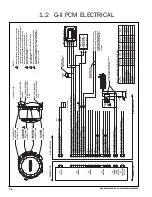
Page 21: ...PLIED WITH CONNECTOR PLUGS ON STANDARD HEATERS 4 ALL CONTROL SIGNAL INPUT VOLTAGES MUST MATCH HEATER SUPPLY VOLTAGE 5 ALL HEATER OUTPUT SIGNALS WILL MATCH HEATER SUPPLY VOLTAGE 6 WIRE USED ON DATALINK CONNECTOR USB CONNECTIONS P3 MUST MEET UNIVERSAL SERIAL BUS CABLES AND CONNECTION STANDARDS REV 2 0 USB WIRES MAXIMUM LENGTH IS 13 1FT 4M RED GREEN WHITE BLACK TIMER OPTION TI OR TII INDICATOR LIGHT ...

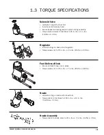
Page 22: ...ricate O ring on nozzle with diesel fuel Torque nozzle to fuel block to 150 in lbs 10 in lbs 16 9 Nm 1 1 Nm Nozzle Assembly Torque nozzle to nozzle stem to 30 in lbs 3 in lbs 3 4Nm 3 Nm Fuel Delivery Block Ensure all three O rings are in place Torque screws 3 to 75 in lbs 7 in lbs 8 5 Nm 0 8 Nm Regulator Install 2 o rings on back side of regulator Torque screws 2 to 75 in lbs 3 in lbs 8 5 Nm 0 3 N...

Page 23: ...ops into fuel pump gear Ensure correct alignment refer to Motor Replacement on page 4 33 Torque bolts 4 to 75 in lbs 7 in lbs 8 5 Nm 0 8 Nm Dual Mode Temperature Sensor Install O ring onto sensor Torque sensor to 100 in lbs 10 in lbs 11 6 Nm 1 1 Nm Burner Head Heat Exchanger Torque bolts 2 to 100 in lbs 10 in lbs 11 6 Nm 1 1 Nm 1 10 PROHEAT M SERIES G II PCM SERVICE MANUAL ...

Page 24: ...mpressor Replacement on page 5 7 Torque screws 2 to 75 in lbs 3 in lbs 8 5 Nm 0 3 Nm Relief Valve for Use with Rotary Vane Compressor ONLY Serial Numbers 600000 699999 Torque to 25 in lbs 3 in lbs 2 8 Nm 0 3 Nm Diaphragm Compressor ONLY Serial Numbers 70000 and above Install O rings in to cylinder head and valve cover not shown Ensure connecting rod is at BDC and ensure the diaphragm is concentric...

Page 25: ...PROHEAT M SERIES G II PCM SERVICE MANUAL 1 12 ...

Page 26: ... air pressure to the Fuel Nozzle Note that older versions of M Series use a rotary vane compressor Refer to page D 1 for more information Electronic Ignition Module with plug in electrode Electronic control module that monitors inputs from the sensors and controls outputs to PROHEAT components It has an integrated Flame Sensor that photo electrically measures the intensity of the flame to determin...

Page 27: ...sor also touches the inner heat exchanger surface to mea sure the heat exchanger temperature for an overheat condition Heat Exchanger Coolant Pump Dual Mode Temperature Sensor G II PCM Air Relief Rotary Vane Compressor ONLY WARNING The Dual Mode Temperature Sensor must be properly installed in the heat exchanger at all times for overheat protection Circulates coolant through the PROHEAT and vehicl...

Page 28: ...G II PCM PROHEAT CONTROL MODULE COMBUSTION TUBE INLET OUTLET HEAT EXCHANGER DUAL MODE TEMPERATURE SENSOR COMBUSTION AIR BLOWER MOTOR BURNER HEAD FLANGE WITH BUILT IN AIR COMPRESSOR AIR FILTER IGNITION ELECTRODES AIR COMPRESSOR ROTARY VANE COMPRESSOR SERIAL NUMBERS 600000 699999 AIR RELIEF Figure 2 1 2 3 PROHEAT M SERIES G II PCM SERVICE MANUAL ...

Page 29: ...of the nozzle all the way to the fuel regulator This negative pressure causes fuel to be siphoned from the fuel regulator like a carburetor float bowl The compressed air and fuel are then mixed at the end of the nozzle into a very fine mist of fuel air that is sprayed into the combustion chamber in the shape of a cone The purpose of the Combustion system is to deliver a metered amount of air to th...

Page 30: ... air blower remains constant resulting in a lean air fuel mixture and possibly gray white smoke from the exhaust A decrease in the compressor air pressure over the nozzle will reduce the amount of atomized fuel air into the combustion tube however the combustion air provided by the combustion air blower remains constant resulting in a lean air fuel mixture and possibly gray white smoke from the ex...

Page 31: ...ct range electrical components for over load and for a flame presence Also during the first Pre check the Ignition Module sparks for five seconds to allow a service technician to visually check for a spark If there are no errors indicated the PROHEAT goes to Ignition The Motor and Coolant Pump start first followed by the ignition spark and then Fuel Solenoid Valve opens The Ignition Module sparks ...

Page 32: ... to start again moving into Pre check after Cool Down Purge If the second start cycle fails the PROHEAT will enter Fault Shut Down The PROHEAT will continue in Full Output until the coolant temperature reaches 185 F 85 C at the PROHEAT S Dual Mode Temperature Sensor The PROHEAT closes the Fuel Solenoid Valve and goes into Cool Down Purge 1 Momentary Switch ON Preheat Mode Signal 2 Pre check 3 Igni...

Page 33: ...remains below 160 F 71 C after 30 seconds the PROHEAT goes to Pre check with the coolant pump on The G II PCM performs self diagnosis checking sensors for correct range electrical components for over load and for a flame presence Also during the first Pre check the Ignition Module sparks for five seconds to allow a service technician to visually check for a spark If there are no errors indicated t...

Page 34: ... continuously monitors the coolant temperature If the coolant temperature drops below 160 F 71 C the G II PCM will enter the cycle starting at Pre run The PROHEAT will continue to repeat Steps 2 to 6 until it is switched OFF If the coolant pump is requested on via the coolant pump input analog or CAN the PROHEAT enters Standby coolant pump on If the coolant temperature drops below 160 F 71 C the P...

Page 35: ...2 10 PROHEAT M SERIES G II PCM SERVICE MANUAL ...

Page 36: ...ice Tools 1 Remote Start Switch P N PK0091 2 Temperature Sensor P N 200304K for G II PCM 3 Test Gauge Air Pressure Digital Manometer P N PK0036 4 Test Gauge Air Fuel Pressure P N PK0067 5 Test Gauge Adaptor P N PK0071 Rotary Vane Compressor Models ONLY SN 600000 to 699999 3 1 PROHEAT M SERIES G II PCM SERVICE MANUAL Figure 3 1 Air Pressure Digital Manometer Remote Start Switch Temperature Sensor F...

Page 37: ...blade Allen Key 4 mm 3 8 drive or extension T handle Allen Key 5 mm 3 8 drive or extension T handle Allen Key 9 64 2x Combination Wrench 3 4 Combination Wrench 5 8 Combination Wrench 9 16 Combination Wrench 7 16 Wire Brush Adjustable Wrench Vise Grip Torque Wrench 25 150 in lbs 2 8 17 Nm NOTICE Additional standard hand tools may be required This list is not intended to be exhaustive ...

Page 38: ... an indicator light will flash a diagnostic code Go to page 4 3 If the indicator light flashes count the number of flashes and refer to the troubleshooting diagnostic code description for that number on the following pages If the PROHEAT runs but is not performing or operating correctly consult the Operational Problems section page 4 39 Troubleshooting and Repair Tools Required Test Gauge Air Pres...

Page 39: ...Timer red manual light T II Timer will also display the code on LCD or OEM indicator light installation options will flash 7 times pause and then 10 times G II PCM STATIUS STATE LIGHT COLOUR GREEN Flash Twice Power Up When power is first applied fast then off to the G II PCM the Green LED will flash fast twice to indicate that the G II PCM has booted up GREEN On Solid Heater is switched on Via ana...

Page 40: ...ter 10 consecutive start faults 2 Flame Out page 4 23 3 Coolant Flow page 4 24 4 Overheat page 4 25 Lockout mode on first occurrence 5 Voltage page 4 26 6 Flame Fault page 4 27 Component Diagnostics 7 Temp Sensor Coolant Flow page 4 27 8 Fuel Solenoid page 4 29 9 Not Used page 4 29 10 Ignition Module page 4 30 11 Coolant Pump page 4 31 12 Motor page 4 32 13 Auxiliary Output page 4 34 14 Accessory ...

Page 41: ...OHEAT does not detect proper flame during the 30 second ignition period and the PROHEAT enters Fault Detection Cool Down Purge 3 Ignition GREEN The PROHEAT always restarts after one error detection with the exception of Code 4 overheat After the 3 minute Cool Down Purge the PROHEAT will go through Precheck Ignition and the Fault Detection Cool Down Purge cycle one more time 5 Steps 2 to 4 are Repe...

Page 42: ...ied to exit Lockout mode Fuel and fuel supply Check See Theory of Operation on page 2 4 for fuel system schematic and description a Vehicle fuel level and or for fuel gelling during cold weather b Air leaks and or restrictions in the fuel supply lines to the PROHEAT c The PROHEAT operation when supplying fuel from a direct source Test Procedure Supplying fuel from a remote source a Remove the fuel...

Page 43: ...r O rings and inlet adapter Tighten the adapter until it bottoms out against the face g Reconnect the fuel supply line h Switch the PROHEAT on and operate for at least one complete cycle Observe the operation If a Start diagnostic code is indicated proceed to Step 3 START Fuel System Step 2 1 Flash Figure 4 4 Fuel Filter Assembly and Location O RING FILTER ADAPTER TORQUE SEE SECTION 1 3 O RING INL...

Page 44: ... disassembly inspection cleaning and reassembly Hold the Fuel Nozzle stem lightly but firmly in a vise using soft jaws take care not to cause damage Disassembles in three pieces Inspect Fuel Nozzle stem and O ring for contamination and or damage Inspect and clean distributor fuel orifice a soft bristled brush may be used air passages head and stem with electrical contact cleaner or warm soapy wate...

Page 45: ...ears on the bolts i Tighten mounting bolts See Section 1 3 for torque j Reconnect the electrical harnesses and fuel supply line k Switch the PROHEAT on and operate for at least one complete cycle Observe the operation If a Start diagnostic code is indicated proceed to Step 4 Figure 4 7 Fuel Nozzle Assembly FUEL NOZZLE ORIFICE AIR PASSAGES AIR PASSAGES FUEL AND AIR OUTLET ORIFICE HEAD DISTRIBUTOR S...

Page 46: ... II PCM Test Procedure Air Compressor pressure all models a Disconnect all harnesses at the G II PCM b Disconnect the fuel supply line c Loosen and back out the burner head mounting 2 bolts five to six turns allowing enough room to rotate the burner head 15 counter clockwise and remove d Remove Ignition Electrode Assembly Use a flat head screwdriver to pry the electrode assembly out e Remove the F...

Page 47: ... Connect Power Harness and Remote Switch to the G II PCM k Switch the PROHEAT on and observe the air pressure l Adjust the air pressure if necessary by turning the screw as shown in Figure 4 9 If the pressure cannot be set to the correct setting rebuild kits are available See www proheat com for the latest parts manual SL9151 for more information m Turn heater off Wait until Cool Down Purge mode i...

Page 48: ...r with the remote switch and observe operation The heater should run smoothly with no smoke although there may be some hesitation initially due to air in the fuel line q Remove the remote switch and re connect the control connection If a Start diagnostic code is indicated proceed to Step 5 MODEL AIR PRESSURE ROTARY VANE COMPRESSOR M50 6 2 0 1 PSI 42 7 0 7 kPa M80 3 2 0 1 PSI 22 1 0 7 kPa M105 3 8 ...

Page 49: ...rness Lubricate Air Pressure Relief Valve O ring with diesel fuel and re install the Air Pressure Relief Valve in it s original location Torque to 25 in lbs 3 in lbs 2 8 Nm 0 3 Nm Reconnect the Ignition Module and Fuel Solenoid connectors to the G II PCM Re install the Flame Shield the Ignition Electrode Assembly and Burner Head onto the Heat Exchanger q Connect the Power Dual Mode Temperature Sen...

Page 50: ... Fuel Solenoid Valve connector Use a small flat head screwdriver to lift the connector locking tab pulling up on the connector to remove START Fuel System Step 5 1 Flash Figure 4 14 G II PCM Fuel Solenoid Valve Connection G II PCM FUEL SOLENOID VALVE CONNECTION NOTICE It is recommended that the Fuel Regulator be serviced at the same time as the Fuel Solenoid Valve Go to page 4 15 Step 6 Figure 4 1...

Page 51: ...c Inspect the O ring and plunger seat in the fuel block for contamination Clean as necessary using plastic safe electrical contact cleaner d Install the new valve stem with plunger and seal using a slot screwdriver e Reinstall the coil coil nut and reconnect the Fuel Solenoid Valve connector at the G II PCM f Reinstall the burner head by mounting it against the heat exchanger face turning clockwis...

Page 52: ...L d Remove the Ignition Electrode then the Flame Shield c Disconnect the Fuel Solenoid Valve from the PCM e To prevent contamination clean area around the base of the Fuel Delivery Block prior to disassembly Blow all loose debris off with compressed air prior to disassembly f Remove the Fuel Delivery Block by removing the three M6 screws and three Lock Washers Be careful not to lose the gears or I...

Page 53: ...ockwise to engage the mounting ears on the bolts q Reconnect the electrical harnesses and fuel supply line r Switch the PROHEAT on and operate for at least one complete cycle Observe the operation If a Start diagnostic code is indicated proceed to Step 7 NOTE LUBRICATE O RINGS WITH DIESEL FUEL PRIOR TO INSTALLATION NOTE INLET SCREEN AND O RING ASSEMBLY ORDER BLOWER HOUSING COMPRESSOR FLANGE FLAME ...

Page 54: ...the G II PCM i Reconnect the fuel supply line j Switch the PROHEAT on and read the fuel pressure should be 5 10 PSI If the pressure is out of range Go to Fuel Supply Pump cleaning page 4 18 If the pressure reads OK review Fuel System troubleshooting page 4 5 START Fuel System Step 7 1 Flash Figure 4 19 Burner Head Removal and Fuel Pressure Test GAUGE P N PK0067 FUEL SUPPLY PUMP TEST PORT FUEL SOLE...

Page 55: ...ne o Switch the PROHEAT on and operate for at least one complete cycle Observe the operation Fuel Supply Pump Gear Check Replacement a Disconnect all harnesses at the G II PCM b Disconnect the fuel supply line c Loosen and back out the Burner Head mounting 2 bolts five to six turns allowing enough room to rotate the Burner Head 15 counter clockwise and remove d Remove the Ignition Electrode then t...

Page 56: ... heater unit and operate for a minimum of two cycles to ensure functionality Inspect for fuel leaks around exterior of Burner Head and Heat Exchanger NOTE LUBRICATE O RINGS WITH DIESEL FUEL PRIOR TO INSTALLATION NOTE INLET SCREEN AND O RING ASSEMBLY ORDER BLOWER HOUSING COMPRESSOR FLANGE FLAME SHIELD IGNITION ELECTRODE GEARS O RING O RING O RING O RING O RING SCREEN SCREEN O RING 3 x M6SCREWS TORQ...

Page 57: ...witch harnesses only START Ignition System 1 Flash WARNING Shock hazard due to high voltage WARNING To avoid flame DO NOT re connect Dual Mode Temperature Sensor when Burner Head is removed Figure 4 22 Burner Head Removal and Ignition Electrode Removal MOUNTING EARS 2 MOUNTING BOLTS 2 TORQUE SEE SECTION 1 3 COOLANT PUMP SWITCH INPUT DUAL MODE TEMP SENSOR POWER FUEL INLET 173 4 4 mm 935 23 5 mm 1 0...

Page 58: ...for contamination on the Flame Sensor Clean if necessary using electrical contact cleaner and a soft cloth f Reconnect the power harness WARNING To avoid the risk of shock and to ensure that the PROHEAT does not fire disconnect the Ignition Module connector at the G II PCM Flame Sensor Check a Flame Sensor operation b Combustion tube orientation Test Procedure Flame Sensor circuit a Disconnect all...

Page 59: ...flashlight into the sensor the G II PCM status light should come on Green If the G II PCM status light reacts correctly the Flame Sensor is OK Go to Test Procedure Combustion Tube orientation If the G II PCM status light does not react the Flame Sensor is faulty Go to G II PCM replacement page 4 38 Test Procedure Combustion Tube orientation a Ensure that the combustion tube orientation boss is ali...

Page 60: ...ame Out diagnostic code is displayed A Flame Out diagnostic code distinguishes that a A flame was detected therefore there was a spark and the Ignition system works b The flame was detected therefore the Flame Sensor works c The fault is in the fuel supply system Troubleshoot the Flame Out diagnostic code based on 1 Fuel supply to the PROHEAT Go to page 4 5 page 4 6 Step 1 2 Fuel tank pick up Fuel...

Page 61: ...Coolant Pump and the engine Coolant Pump pumping in the same direction when they are operating at the same time f Coolant capacity Is there enough coolant in the system Go to Technical Specifications page 1 1 g PROHEAT location Is the PROHEAT or Coolant Pump the high point in the system Coolant Pumps are not self priming and a surge tank may be required Coolant Pump and G II PCM Check a G II PCM e...

Page 62: ...the heater is not switched on Troubleshoot the Overheat diagnostic code based on 1 Lack of coolant air or flow problems in the coolant system Go to page 4 24 Steps 1 and 2 2 Faulty Temperature Sensor Go to page 4 27 3 Faulty G II PCM Temperature Sensor circuit Go to page 4 27 An Overheat will put the heater in Lockout Mode requires power to the G II PCM to be removed and reapplied on the first occ...

Page 63: ...he vehicle engine is running High Voltage Check The vehicle charging system Consult the OEM for service requirements Low Voltage Check a System voltage supply source b Wiring harnesses and connection points Procedure Low voltage testing a Inspect the wiring harnesses and connections for corrosion and proper fit Clean if necessary b Using a multimeter set for voltage measure across the positive and...

Page 64: ...ected 2 The PROHEAT was switched on and a flame signal was detected in Pre check Troubleshoot the Flame Fault diagnostic code based on 1 Fuel Solenoid Valve mechanical fault Go to page 4 29 2 Glowing carbon deposits inside the combustion tube Go to page 5 2 and preform the complete annual maintenance procedure 3 G II PCM Flame Sensor circuit Go to page 4 21 TEMP SENSOR COOLANT FLOW Diagnostic Code...

Page 65: ...e the coolant system at the PROHEAT inlet and outlet ports for minimal coolant loss using valves in the system or hose clamps b Remove main sensor mount using a 1 wrench c Reinstall the new sensor Ensure that the O ring and O ring seat are clean Install the sensor until it bottoms out on the mounting boss If after changing the Temperature Sensor a diagnostic code is still indicated the G II PCM is...

Page 66: ...noid Valve and G II PCM test a Disconnect all harnesses at the G II PCM b Disconnect the fuel supply line c Loosen and back out the burner head mounting 2 bolts five to six turns allowing enough room to rotate the burner head 15 counter clockwise and remove d Disconnect the Fuel Solenoid Valve connector at the G II PCM e Inspect the G II PCM connector for damage and corrosion Inspect the Fuel Sole...

Page 67: ...Module is faulty Go to Ignition Module replacement this page 4 1 11 10 Flashes Figure 4 32 Burner Head Removal and Ignition Module Replacement MOUNTING EARS 2 MOUNTING BOLTS 2 TORQUE SEE SECTION 1 3 COOLANT PUMP SWITCH INPUT DUAL MODE TEMP SENSOR POWER FUEL INLET NOTICE All plugs harnesses must be rein stalled into the G II Proheat Control Module G II PCM before heater goes back into service IGNIT...

Page 68: ... the Coolant Pump using shut off valves provided in the coolant system or hose to minimize coolant loss b Remove Coolant Pump c Install new Coolant Pump 4 1 12 11 Flashes Figure 4 33 G II PCM Coolant Pump Connection G II PCM COOLANT PUMP CONNECTION CAUTION DO NOT run a coolant pump dry Before starting the PROHEAT ensure that the Coolant Pump is flooded with coolant by opening all valves and runnin...

Page 69: ...Compressor by removing the Motor Go to Motor replacement page 4 33 Then rotate the motor by hand checking for mechanical binding If the Motor spins freely and there are no obvious mechanical problems check the Motor G II PCM electrical connection Go to Test Procedure G II PCM and motor connector and harness Test Procedure G II PCM and Motor Connector and Harness a Disconnect the Motor connector at...

Page 70: ...g snap ring and gear from the old Motor and install on the new Motor j Install the new Motor Take care when installing the Motor shaft in the Fuel Supply Pump seal Lubricate with clean diesel fuel k Reinstall 4 screws l Reconnect the Motor connector at the G II PCM m Reinstall the blower blower retaining snap ring Air Compressor filter and blower housing Figure 4 35 Motor Replacement BLOWER BLOWER...

Page 71: ... the G II PCM b Switch the PROHEAT on and operate for at least one complete cycle Observe the operation If the diagnostic code is not indicated the fault is in the harness or the driven device Go to OEM for service requirements If the diagnostic code is still indicated the G II PCM is faulty Go to G II PCM replacement page 4 38 Figure 4 36 Auxiliary Output Connector G II PCM AUXILIARY OUTPUT CONNE...

Page 72: ...r 5 seconds while normal less than 12 Amps current is flowing through the motor Troubleshoot the Motor Speed Sensor code based on a Inspect the Combustion Air Blower magnet for damage b Motor mechanical function Go to page 4 32 and perform Test Procedure Motor mechanical function If the Motor Speed Sensor Diagnostic Code 15 is still indicated the G II PCM is faulty Go to G II PCM replacement page ...

Page 73: ... 1 Voltage supply to the PROHEAT 2 Voltage at the output connections of the G II PCM Test Procedure Voltage supply a Disconnect the power harness at the G II PCM b Using a multimeter set for voltage measure across pins A and B of the harness connector for system voltage If there is no voltage check the OEM voltage supply Consult OEM for service requirements If the correct voltage system voltage 12...

Page 74: ...el supply line ci G II PCM Locate and measure across pins C and E in the G II PCM Data Link connection Perform this with the PROHEAT off and then switched on If the voltage is within the operating range and a Voltage diagnostic code is indicated the G II PCM is faulty Go to G II PCM replacement page 4 38 If the voltage falls below the required voltage when the Motor starts check the wiring from th...

Page 75: ... ring and slide the blower off the Motor shaft d Remove the Air Compressor filter e Disconnect the Motor connector at the G II PCM Remove the G II PCM f Reinstall the new G II PCM following items e back to a g Reconnect the burner head by mounting it against the heat exchanger face turning it clockwise to engage the mounting ears on the bolts h Reconnect electrical harnesses and fuel supply line i...

Page 76: ...three categories 1 Fuel Supply Combustion Go to page 4 5 to page 4 33 Steps 1 to 7 Smoke from the exhaust Excessive raw diesel odor Backfiring and coughing during the combustion process Low heat output 2 Coolant system Go to page 4 24 Steps 1 and 2 Short combustion cycles The PROHEAT is turning on and off at very short intervals Low heat output in the vehicle system Go to page 4 5 to page 4 33 Ste...

Page 77: ...PROHEAT M SERIES G II PCM SERVICE MANUAL 4 40 ...

Page 78: ...ery power draw Long term cost savings Increased reliability Check the system annually before each heating season There are several maintenance procedures you can perform to keep your heater in service Read this section of the manual carefully NOTICE The flame hours can be determined from the G II PCM data download PK0064 is required to download the G II PCM data See the parts book at www proheat c...

Page 79: ...pect and clean the inside and outside of the combustion tube To maintain optimum heat output clean any combustion deposits that may have accumulated on the heat exchanger fins Use a wire brush to loosen the deposits and a vacuum to suck them out Ensure exhaust pipe is clean and free from restriction Alternate heat exchanger cleaning method The inside of the heat exchanger exhaust pipe may be clean...

Page 80: ...m and O ring for contamination and or damage Replace if damaged Disassemble Nozzle inspect and clean distributor a soft bristled brush may be used fuel orifice air passages head and stem with electrical contact cleaner or warm soapy water DO NOT use a welding torch tip cleaner Refer to page 4 7 FUEL FILTER O RING O RING ADAPTER TORQUE 100 10 IN LBS 11 3 1 1 NM INLET FITTING TORQUE 100 10 IN LBS 11...

Page 81: ... if dusty conditions are encountered Ensure the air filter is seated correctly into the PCM Refer to page 4 9 Step 6 AIR FILTER Figure 5 5 Air Filter Figure 5 6 Compressor Check 10 Compressor Diaphragm Compressor Shown For Rotary Vane Compressor please see the M Serise Service manual Important Complete steps 8 and 9 prior to step 10 compressor check Ensure Blower Housing Cover is installed before ...

Page 82: ...al Check the air pressure setting as described on page 4 9 WARNING Flammable Point Nozzle away from face open sparks and flames MODEL AIR PRESSURE DIAPHRAGM COMPRESSOR M50 6 0 0 1 PSI 41 4 0 7 kPa M80 90 2 9 0 1 PSI 20 0 0 7 kPa M105 125 3 65 0 1 PSI 25 1 0 7 kPa 11 Electrical System Check the internal and the external wire harnesses for missing or damaged seals damage and corrosion Replace if req...

Page 83: ... 200610K 1 Filter Air Element 880035K 1 Fuel Filter PK0036 1 Digital Manometer PK0067 1 Test Gauge Air Fuel Pressure PK0091 1 Remote On Off Switch PK0071 1 Test Gauge Adapter Rotary Vane Compressor Models ONLY SN 600000 to 699999 REPLACEMENT PARTS AND TEST EQUIPMENT ...

Page 84: ...out the burner head mounting 2 bolts five to six turns allowing enough room to rotate the burner head 15 counter clockwise and remove the Burner Head to a workbench e Remove blower housing 2 screws and blower housing f Remove the Air Compressor filter Inspect for contamination and replace if necessary Clean the filter cavity and the air passages using a dry cloth g Remove ignition electrode assemb...

Page 85: ...ent DO NOT USE BRAKE CLEAN as it will damage the compressor spray directly into intake of compressor Spray the cleaner and run the motor for at least 30 seconds to remove all of the vane dust and cleaner Figure 5 8 Compressor Cleaning WARNING Failure to disconnect the ignition module will cause a spark that may cause a fire Ensure to disconnect ignition module REMOVE BLOWER REMOVE AIR FILTER DISCO...

Page 86: ...ction 1 3 for torque l Reinstall flame shield and electrode m Reinstall the air filter and blower n Reinstall the blower housing 9 64 HEX HEAD SCREW 3 WEAR PLATE SCREW 3 DO NOT LOOSEN SEE NOTICE BODY BORE ROTOR END PLATE VANES 4 Figure 5 9 Compressor Components 3 Test Air Compressor a Test the air pressure setting as shown on page 4 11 b If pressure cannot be set correctly proceed to step 4 5 9 PR...

Page 87: ...RAKE CLEAN f Use a clean dry cloth to remove flushing solvent from parts g Place new vanes in rotor slots in the proper beveled edge direction h Place a sheet of emery cloth on a smooth flat surface and rub both sides of the Wear Plate located behind the End Plate to remove any burrs Use a clean dry cloth to remove any dust from the Wear Plate i Remove old paint and clean the top surface of the co...

Page 88: ...D TO THE PROHEAT HEATER SYSTEM SEASTAR SOLUTIONS MAKES NO OTHER WARRANTIES EXPRESSED OR IMPLIED OF MERCHANTABILITY OR FITNESS FOR A PARTICULAR PURPOSE OWNER RESPONSIBILITIES Before the expiration of the warranty Owner must give notice to a Registered PROHEAT Dealer of failures if any considered to be warrantable and deliver the defective heater system to such dealer Owner is responsible for the co...

Page 89: ...6 2 PROHEAT M SERIES G II PCM SERVICE MANUAL ...

Page 90: ...d Manufactured in North America SeaStar Solutions 3831 No 6 Road Richmond B C Canada V6V 1P6 Tel 604 270 6899 Fax 604 270 7172 www proheat com Proheat is a registered trademark of Marine Canada Acquisition Inc and its subsidiary companies 2012 Marine Canada Acquisition Inc DBA SEASTAR SOLUTIONS ...

Reviews: