


TDR-X
Operator’s Manual
40
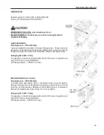
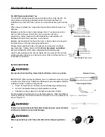
Pro-EZII Replaceable Blade Tips
The Pro-EZII change blade tips are serviceable with a single wrench. An
anti-rotation slot engaging the blade bolt to the blade bar allows for
installation and removal of the nut from one side without having to hold the
bolt.
When removing blade tips, inspect the tips and blade bolts for wear and
damage.
Replace any tip that is bent, nicked deeper than ¼”, excessively worn or
has any other damage. Small nicks can be ground out during
sharpening. Always balance Pro-EZII blades as an assembled unit.
Replace both tips at the same time on one holder.
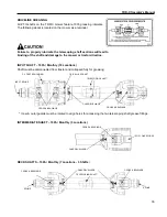
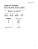
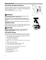
Replace any blade bolts that have the head or blade shank worn beyond
the limits shown in the accompanying illustrations.
Always install new blade bolts, lock washers and nuts when installing
new blade tips. Tighten bolts to 85 ft-lbs
Error! Bookmark not defined.
.
DO NOT OPERATE WITH ONLY ONE BLADE TIP INSTALLED.
Grass build-up between the tip and blade bar may prevent the tip from
pivoting properly at start-up or during mowing. Ensure all tips are free to
rotate prior to operation.
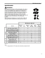
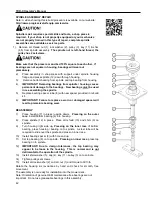
BLADE SHARPENING
Use gloves when handling mower blades. Blades can be very sharp.
IMPORTANT! When sharpening blades, be sure material removed is equal
on both sides of the blade. Unbalanced blades will cause excessive vibration
leading to cracks in machine components.
•
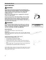
Clean all material from the blade prior to sharpening and balancing.
•
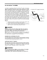
Grind or file blades following original pattern as shown.
•
Sharpen to a razor edge. Do not sharpen back side of blade.
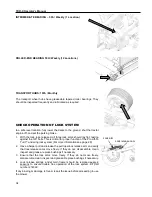
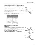
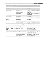
Use the supplied cone balancer to verify blade balance. When the blade is
correctly balanced, the blade will remain horizontal on the cone balancer as
show in Figure 16.
Failure to properly balance blades after sharpening can cause vibration
leading to premature component damage.
Wear appropriate eye and face protection when sharpening blades.
0.12 IN
MINIMUM
Bolt Head Wear Limit
0.03 IN
MAXIMUM
Bolt Shank Wear Limit
Figure 15
– Grind Pattern
Figure 16
Summary of Contents for TDR-X
Page 2: ......
Page 48: ...TDR X Operator s Manual 46 ...
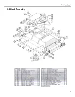
Page 54: ...TDR X Parts Manual 2 1 DECK ASSEMBLY 1 1 Blade Spindle Assembly ...
Page 55: ...TDR X Parts Manual 3 1 2 Deck Assembly ...
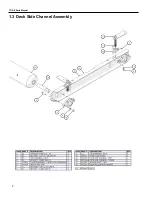
Page 56: ...TDR X Parts Manual 4 1 3 Deck Side Channel Assembly ...
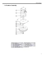
Page 57: ...TDR X Parts Manual 5 1 4 Gearbox Assembly ...
Page 58: ...TDR X Parts Manual 6 2 FRAME ASSEMBLY 2 1 Frame Assembly ...
Page 59: ...TDR X Parts Manual 7 2 2 Hitch Assembly ...
Page 60: ...TDR X Parts Manual 8 2 3 Right Wing Assembly ...
Page 61: ...TDR X Parts Manual 9 2 4 Left Wing Assembly ...
Page 62: ...TDR X Parts Manual 10 2 5 Rear Lift Assembly ...
Page 63: ...TDR X Parts Manual 11 2 6 Lock Release Assembly ...
Page 64: ...TDR X Parts Manual 12 2 7 Wheel Assembly ...
Page 65: ...TDR X Parts Manual 13 3 HYDRAULICS ...
Page 66: ...TDR X Parts Manual 14 4 DRIVELINE 4 1 Driveline Layout ...
Page 67: ...TDR X Parts Manual 15 4 2 Input PTO Shaft ...
Page 68: ...TDR X Parts Manual 16 4 3 Intermediate PTO Shaft ...
Page 69: ...TDR X Parts Manual 17 4 4 Wing Deck PTO Shaft ...
Page 70: ...TDR X Parts Manual 18 4 5 Rear Deck PTO Shaft ...
Page 71: ...TDR X Parts Manual 19 4 6 4 Way Gearbox ...


