


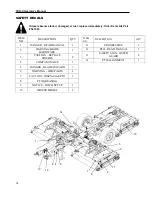


TDR-X
Operator’s Manual
20
HITCHING THE MOWER TO THE TRACTOR
Crushing Hazard between tractor and mower. Never allow anyone
to stand between tractor and mower while backing-up to the
mower
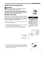
1) With the draw pin placed in the hitch clevis (Figure 3 page 19), back the
tractor to the hitch clevis.
2) When the draw pin holes are aligned, place the tractor controls in the
park position, shut the engine off and engage the parking brake.
3) Remove draw pin from the hitch clevis and place in the draw pin hole
connecting the mower to the tractor.
4) Note always use the provided hitch pin. The flat top design provides
additional clearance to the underside of the input PTO.
Never use hitch
pins with D ring type handle.
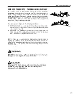
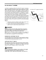
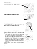
5) Raise parking jack fully and place in storage position (Figure 4).
STOWING THE JACK
The jack cannot be stowed in the parked position while mowing. A second
storage position is provided on the Left-hand deck to avoid damage to the
jack while mowing (Figure 4).
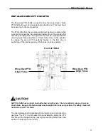
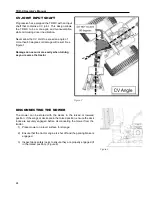
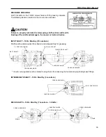
CONNECTING THE PTO TO THE TRACTOR
1) Ensure that the tractor engine is shut off, the parking brake is engaged,
and the mower is securely hitched to the tractor.
2) Lift input PTO shaft from PTO support, ensuring that PTO support
swings down and rests on frame tube.
3) Slide the mower input shaft locking collar backwards, opening the
locking mechanism. Locking collar should remain in an open position
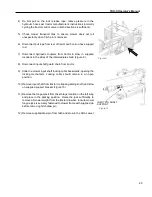
4) When it is safe to do so, hold the PTO against the end of the tractor PTO
shaft, rotate the PTO by hand until the shaft slides on slightly.
5)
Slide the yoke onto the tractor’s PTO.
6) The locking collar should automatically engage when the yoke is
properly engaged with the tractor PTO.
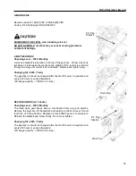
7) Attempt to move the shaft forward and backwards to ensure that it is
securely locked in place.
8) Attach the PTO cover safety chain to the tractor. Ensure cover is
properly retained by the chain on the mower end.
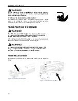
9) The TDR-X is equipped with a PTO support to aid in connecting the
mower to the tractor. Once the PTO shaft is connected to the tractor,
fold the PTO shaft support down onto the frame and secure it with the
supplied cotter pin before operating
– DO NOT LEAVE SUPPORT IN
UPRIGHT POSITION. See Figure 2 page19
If the PTO shaft comes off during operation, it may cause
personal injury and damage to the PTO shaft and tractor PTO.
When checking, make sure the locking collar is locked, and that
the shaft is not just jammed against the end of the tractor PTO
shaft.
Figure 4
Summary of Contents for TDR-X
Page 2: ......
Page 48: ...TDR X Operator s Manual 46 ...
Page 54: ...TDR X Parts Manual 2 1 DECK ASSEMBLY 1 1 Blade Spindle Assembly ...
Page 55: ...TDR X Parts Manual 3 1 2 Deck Assembly ...
Page 56: ...TDR X Parts Manual 4 1 3 Deck Side Channel Assembly ...
Page 57: ...TDR X Parts Manual 5 1 4 Gearbox Assembly ...
Page 58: ...TDR X Parts Manual 6 2 FRAME ASSEMBLY 2 1 Frame Assembly ...
Page 59: ...TDR X Parts Manual 7 2 2 Hitch Assembly ...
Page 60: ...TDR X Parts Manual 8 2 3 Right Wing Assembly ...
Page 61: ...TDR X Parts Manual 9 2 4 Left Wing Assembly ...
Page 62: ...TDR X Parts Manual 10 2 5 Rear Lift Assembly ...
Page 63: ...TDR X Parts Manual 11 2 6 Lock Release Assembly ...
Page 64: ...TDR X Parts Manual 12 2 7 Wheel Assembly ...
Page 65: ...TDR X Parts Manual 13 3 HYDRAULICS ...
Page 66: ...TDR X Parts Manual 14 4 DRIVELINE 4 1 Driveline Layout ...
Page 67: ...TDR X Parts Manual 15 4 2 Input PTO Shaft ...
Page 68: ...TDR X Parts Manual 16 4 3 Intermediate PTO Shaft ...
Page 69: ...TDR X Parts Manual 17 4 4 Wing Deck PTO Shaft ...
Page 70: ...TDR X Parts Manual 18 4 5 Rear Deck PTO Shaft ...
Page 71: ...TDR X Parts Manual 19 4 6 4 Way Gearbox ...


