


TDR-X
Operator’s Manual
19
MOWER SETUP FOR OPERATION
Always refer to tractor operator’s manual for specific detailed
information regarding operation of equipment.
Always ensure the tractor controls are in the park position, the
engine is turned off, the parking brake is engaged and hydraulic
pressure to the tractor remote connectors has been relieved when
working around tractor during setup procedures.
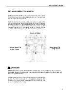
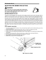
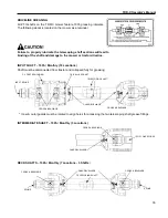
DRAWBAR ADJUSTMENT
Before hitching the mower to the tractor, ensure tractor drawbar is set
properly. Having the proper hitching dimensions for the tractor drawbar
and the PTO, will ensure long and trouble free hours of operation.
Incorrect setup may lead to contact between the mower and PTO
shaft, causing damage to the Input PTO shaft.
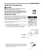
The decal shown in Figure 1 is mounted to the machine and indicates
these important hitch dimensions.
1)
The drawbar length must be adjusted so it is 14” to 15” from the end
of the PTO shaft to the center of the draw pin
2) To ensure sufficient clearance, t
he top of the drawbar must be 6” to
9” from the center of the PTO shaft to the top of the drawbar.
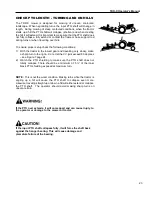
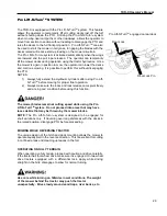
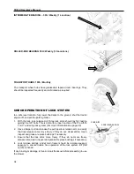
3) To assist in connecting the TDR-X to the tractor, the provided hitch
pin can be temporarily placed in the hitch swivel to hold it level while
aligning the hitch, as shown in Figure 3. Do not operate mower with
the hitch pin in the hitch swivel.
Figure 3
Figure 2
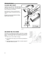
SWIVEL HITCH
DRAW CLEVIS
INPUT PTO SHAFT
SUPPORT
Figure 1
Summary of Contents for TDR-X
Page 2: ......
Page 48: ...TDR X Operator s Manual 46 ...
Page 54: ...TDR X Parts Manual 2 1 DECK ASSEMBLY 1 1 Blade Spindle Assembly ...
Page 55: ...TDR X Parts Manual 3 1 2 Deck Assembly ...
Page 56: ...TDR X Parts Manual 4 1 3 Deck Side Channel Assembly ...
Page 57: ...TDR X Parts Manual 5 1 4 Gearbox Assembly ...
Page 58: ...TDR X Parts Manual 6 2 FRAME ASSEMBLY 2 1 Frame Assembly ...
Page 59: ...TDR X Parts Manual 7 2 2 Hitch Assembly ...
Page 60: ...TDR X Parts Manual 8 2 3 Right Wing Assembly ...
Page 61: ...TDR X Parts Manual 9 2 4 Left Wing Assembly ...
Page 62: ...TDR X Parts Manual 10 2 5 Rear Lift Assembly ...
Page 63: ...TDR X Parts Manual 11 2 6 Lock Release Assembly ...
Page 64: ...TDR X Parts Manual 12 2 7 Wheel Assembly ...
Page 65: ...TDR X Parts Manual 13 3 HYDRAULICS ...
Page 66: ...TDR X Parts Manual 14 4 DRIVELINE 4 1 Driveline Layout ...
Page 67: ...TDR X Parts Manual 15 4 2 Input PTO Shaft ...
Page 68: ...TDR X Parts Manual 16 4 3 Intermediate PTO Shaft ...
Page 69: ...TDR X Parts Manual 17 4 4 Wing Deck PTO Shaft ...
Page 70: ...TDR X Parts Manual 18 4 5 Rear Deck PTO Shaft ...
Page 71: ...TDR X Parts Manual 19 4 6 4 Way Gearbox ...