


TDR-X
Operator’s Manual
22
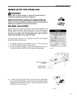
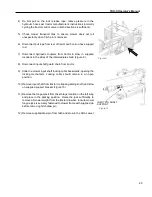
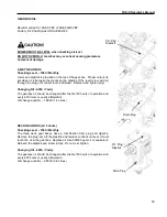
4.1. If one deck does not move, STOP, release the pull rope and
fully raise the decks again. Repeat step 1.
5. If all decks lower, continue lowering the decks to the ground.
6. Once the decks touch the ground, hold the lever and ensure all three
cylinders are fully extended
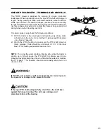
As with any mechanical system, the lock system needs to be used and
maintained properly. With only a few moving parts, this is a simple task.
In a safe level location, fully lower the decks to the ground, shut the
tractor engine off, and set the parking brake.
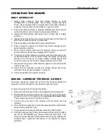
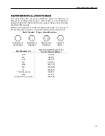
With the lock rope released, all three lock arms should lay flat, resting
against the
3/8” bolts. This is critical for proper function of the Pro Lift-N-
Turn
™ system.(Figure 5)
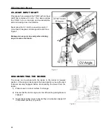
Check each of the three lock arms and release cams making sure they
do not bind when the lock release rope is pulled or released.
Ensure that the lock arms, release cams, cables and springs are in good
condition and move freely.
Check to see if the lock release pull arm is free to rotate without binding
and returns to a neutral position so that the deck lock arms can lay flat
against the wing frame.
If any binding or damage is found, repair the issue before proceeding to
use the mower
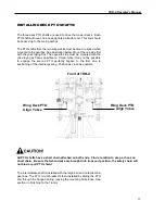
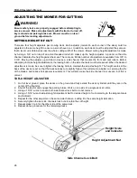
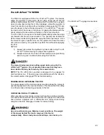
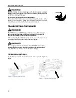
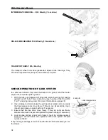
TRANSPORT LOCK
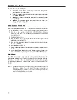
When the decks are in the fully raised position and the pull rope released
(slack), the lock arms engage with each wing and the rear lift to ensure
they do not lower when hydraulic pressure is relieved. (Figure 6)
Never stand beneath the mower decks when placed in the
transport position.
Pro Lift-N-Turn
TM
Position
Figure 5
Lock Pin
Locked Transport Position
Figure 6
Summary of Contents for TDR-X
Page 2: ......
Page 48: ...TDR X Operator s Manual 46 ...
Page 54: ...TDR X Parts Manual 2 1 DECK ASSEMBLY 1 1 Blade Spindle Assembly ...
Page 55: ...TDR X Parts Manual 3 1 2 Deck Assembly ...
Page 56: ...TDR X Parts Manual 4 1 3 Deck Side Channel Assembly ...
Page 57: ...TDR X Parts Manual 5 1 4 Gearbox Assembly ...
Page 58: ...TDR X Parts Manual 6 2 FRAME ASSEMBLY 2 1 Frame Assembly ...
Page 59: ...TDR X Parts Manual 7 2 2 Hitch Assembly ...
Page 60: ...TDR X Parts Manual 8 2 3 Right Wing Assembly ...
Page 61: ...TDR X Parts Manual 9 2 4 Left Wing Assembly ...
Page 62: ...TDR X Parts Manual 10 2 5 Rear Lift Assembly ...
Page 63: ...TDR X Parts Manual 11 2 6 Lock Release Assembly ...
Page 64: ...TDR X Parts Manual 12 2 7 Wheel Assembly ...
Page 65: ...TDR X Parts Manual 13 3 HYDRAULICS ...
Page 66: ...TDR X Parts Manual 14 4 DRIVELINE 4 1 Driveline Layout ...
Page 67: ...TDR X Parts Manual 15 4 2 Input PTO Shaft ...
Page 68: ...TDR X Parts Manual 16 4 3 Intermediate PTO Shaft ...
Page 69: ...TDR X Parts Manual 17 4 4 Wing Deck PTO Shaft ...
Page 70: ...TDR X Parts Manual 18 4 5 Rear Deck PTO Shaft ...
Page 71: ...TDR X Parts Manual 19 4 6 4 Way Gearbox ...


