


Transporting the machine
Profihopper PH4WDi BAF0012.0 02.13
33
4
Transporting the machine
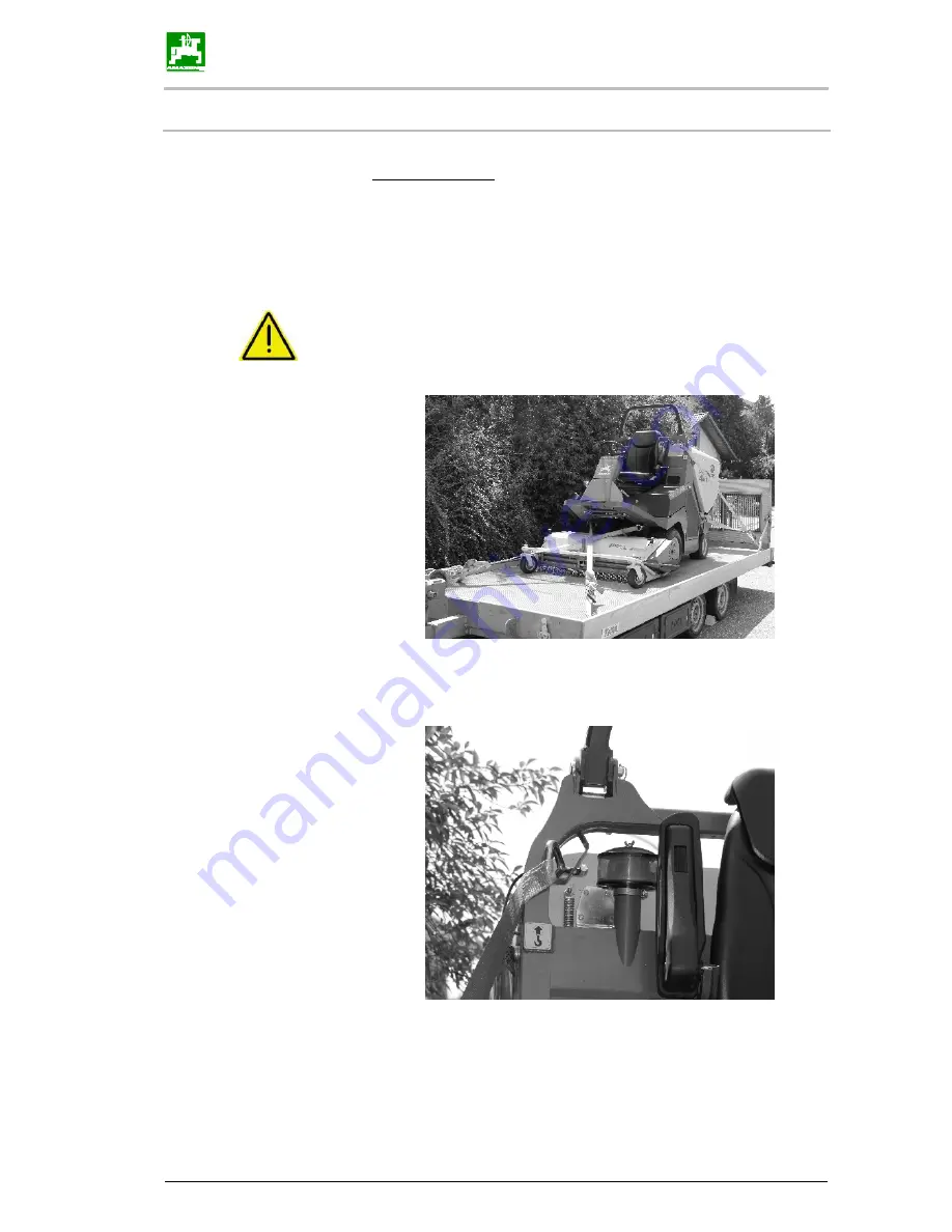
Transport, storage
1. If the machine should be loaded on a trailer, ramps with a gripping,
non-slip surface and the same angle of inclination (16.7°
≙
30%) must
be used.
2. You must exercise particular care and drive slowly when manoeu-
vring up onto a trailer or HGV.
CAUTION!
The machine must always be loaded or driven in
straight ahead direction of travel.
3. For transport on a trailer, the machine must be firmly lashed, the
parking brake must be engaged and the motor switched off. Comply
with the specified lashing points.
Summary of Contents for 4WDi
Page 23: ...General safety instructions Profihopper PH4WDi BAF0012 0 02 13 23...
Page 40: ...Instrument panel and controls 40 Profihopper PH4WDi BAF0012 0 02 13...
Page 78: ...Maintenance 78 Profihopper PH4WDi BAF0012 0 02 13 Height adjustment Fig 10 6 2 13...
Page 82: ...Maintenance 82 Profihopper PH4WDi BAF0012 0 02 13 10 10 Maintenance plan...