


User Guide
DVS-21
02/2018
• V.1.0 • L. Wolle
57/131
© 2017 ProCom
®
Professional Communication & Service GmbH • Technical changes reserved.
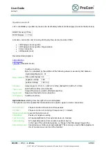
Determining the threshold
In order to determine the threshold, the amp can transfer its own level. The values are sent at one-second
intervals and are displayed on a diagram. The program creates a recommendation for the threshold.
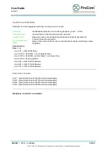
Recommended Programs
Public address:
V100-Impedance measurement:
measurement)
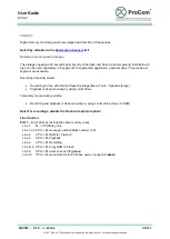
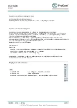
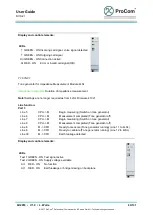
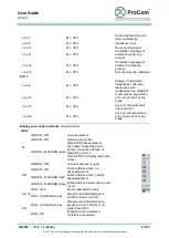
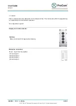
Display and control elements:
LEDs
On GREEN - ON Amp on, PA active
Al RED - ON
Error (no power supply, overload, impedance error)
≈ GREEN - ON Level display
≈ RED - ON
Overload display
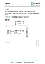
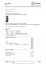
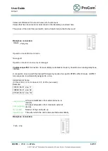
Backplane connectors:
SPK1 1. Amplifier
SPK2 2. Amplifier
SPK3 3. Amplifier
SPK4 4. Amplifier
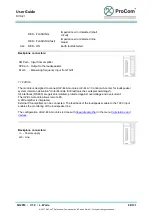
Connection V4 is connected only on the first segment of BPE07 (7-fold expansion)!
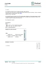
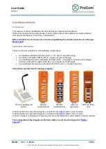
For use with
Standby amplifier
there is a 2-pin connection on the backplane to all amplifiers, to which
the
Standby amplifier
switches its output. At each amplifier slot, this disaster line is segmented by
solder bridges(
HV
x). They must be closed at the
Standby amplifier
and at those all amplifiers that are
involved in the disaster plan.
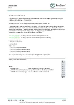
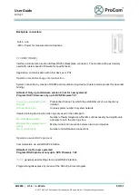
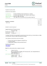
On the backplane BPE07 (extension for 7 V100) the disaster line is segmented by more solder bridges
(
HG
x). They have to be closed all or partially, but always in pairs.
This photo shows the solder bridges for use with
Standby amplifier
!


