


User Guide
DVS-21
02/2018
• V.1.0 • L. Wolle
35/131
© 2017 ProCom
®
Professional Communication & Service GmbH • Technical changes reserved.
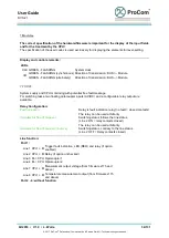
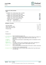
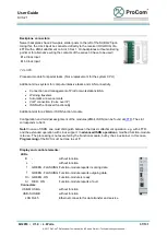
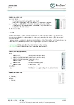
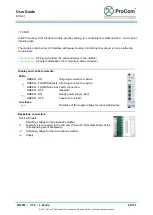
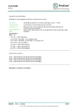
Display and control elements:
LEDs
+5V
GREEN - ON Internal supply voltage is available
GREEN - OFF Failed internal supply voltage
-5V
GREEN - ON Internal supply voltage is available
GREEN - OFF Failed internal supply voltage
U
GREEN - ON Supply voltage available (48V)
GREEN - OFF Power supply failure (48V)
Al
RED - OFF
No malfunctions
RED - ON
System reports a fault
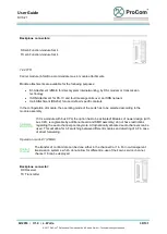
Backplane connectors:
CC Center contact
NO Normally open contact
NC Normally closed contact
OC Optocoupler
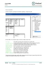
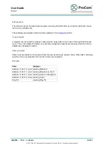
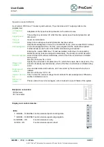
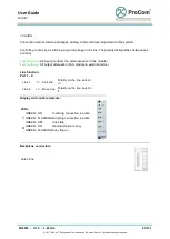
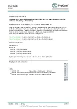
7.2 CPU
Processor Unit
Init. for fault report
lines in loop
Default: 200 (Main loop passes unit)
Time in which the V25 attempts to initialize the supplementary error message-Line,
before the error message program switches from init. to the idle state.
init. time for
modules (sec)
Default: 10
Time for which the V25 pauses in rapid-blinking mode, if all modules are not in the
system.
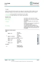
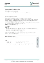
Standby CPU
Interval (x131ms)
Default: 2
Time delay in which the V25 of a standby CPU waits until the "Life data ack." is
sent. Required in standby-systems for differentiation of the CPUs.
Module check
Default: 0 (deactivated)
Time in which the V25 sends test telegrams to the modules, in order to check them.
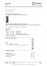
AF Delay (x131ms)
(Concerns only the Loudspeaker program)
Time after which the
Public address
program switches the AF input. (after output
and
Output flag
)


