


Instruction Manual
ViscoTwin
Appendix
ViscoTwin 70_IM_
May 2015
KD
01/2014
Appendix Page A-5
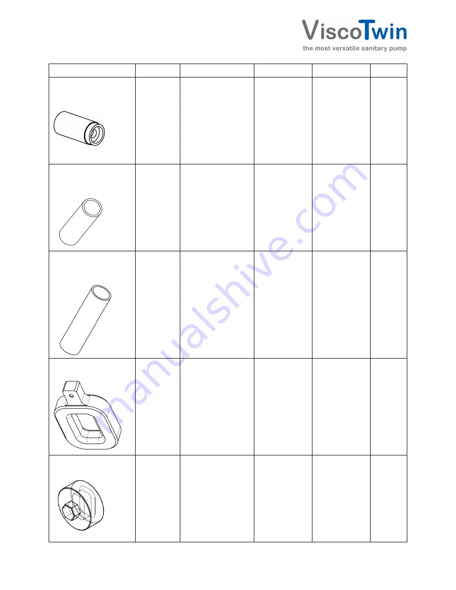
Tool
Tool No.:
Drawing number
Pump model
Item Number
Material
Installation pin for
bearing crown shaft
ring gasket
T 1
T 2
T 3
1011-718
1011-772
1011-773
# 070
# 104
# 130
95578
95579
95580
1.4301
Installation pipe for
needle roller bearing
outer ring
T 11
T 31
T 32
1011-416
1011-417
1011-418
# 070
# 104
# 130
95553
95548
95551
1.4301
Installation
pipe
bearing housing shaft
ring gasket
T 15
T 27
T 28
1011-419
1011-420
1011-421
# 070
# 104
# 130
955547
95545
95546
3.1645
Spindle key without
hexagon
T 35
T 37
1010-823
1010-820
# 070#
# 104 / # 130
40706
40705
3.1645
Spindle
key
with
hexagon
T 36
T 38
1011-124
1011-125
# 070
# 104 / # 130
41106
41107
3.1645


