background image

Usage instructions SPEEDY F4 & F2 


34


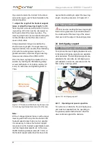
22.2  Caster wheels flapping 

Uncontrolled swivelling backwards and for-
wards of the caster wheels around their axes 
on the caster fork (while moving) is known as 
"fluttering". 


 If the caster wheels start to flutter, imme-

diately reduce your speed to prevent the caster 
wheels from jamming sideways and therefore 
reduce your risk of falling. 


The 

speed limit

 where caster wheel fluttering 

starts, 

is reduced by

  increasing size of the caster wheels 

  increase weight of the caster wheels 

  falling load on the caster wheels 

  decreasing caster length of caster wheels 


The following options are available to 

coun-

teract caster fluttering generally

  When the product is equipped with angle-

adjustable caster-wheel bearing blocks 
(and also with welded caster-wheel bear-
ing blocks, depending on the caster fork 
equipment), fluttering can be reduced by 

reducing the diameter of the caster 
wheels

. This means installing a small 

caster wheel in a different wheel position in 
the caster fork (seat height therefore does 
not change) would be one way of reducing 
fluttering. However, please note that using 
a smaller caster wheel makes it more diffi-
cult to overcome obstacles and makes tip-
ping necessary more often. The smaller 
the caster wheel is, the more driving skill is 
required. 

  Another way to reduce the fluttering is the 

use of a 

lighter caster wheel of the same 

diameter

, or, as previously described, 

with a smaller diameter

 (smaller diameter 

only possible where the product has been 
fitted with angle-adjustable caster-wheel 
bearing blocks). 


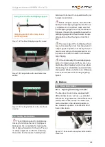
Figure 89: Caster length 


  When fitting the product with angle-

adjustable caster-wheel bearing blocks, 
the 

caster length can be increased

. The 

caster length is the distance between the 
rotary axle of the caster fork projected onto 
the floor and the wheel contact point. The 
wheel contact point of the caster wheel 
trails behind the rotary axle as it were. The 
caster length has a stabilizing effect on 
moving in a straight line. Increasing the 
caster length can be achieved by mounting 
the caster wheel in a different wheel posi-
tion on the caster fork (in doing so, the 
front seat height or the angle of the seat 
changes; see Chapter 17). Another possi-
bility is to bend the caster wheel axle (see 
Chapter 22.4) forwards in the direction of 
travel in the lower area. The angle of the 
caster wheel axle can be adjusted up to 
approximately 4 mm over the length of the 
caster wheel bearing block out of the verti-

Caster wheel for rotary axle 

Caster length 

Wheel contact 
point 

Summary of Contents for SPEEDY F2

Page 1: ...Usage instructions SPEEDY F4 F2 0 Usage instructions Service booklet SPEEDY F4 SPEEDY F2...

Page 2: ...ions while driving using 10 14 Safety instructions regarding obstacles 11 15 Safety instructions regarding dangerous locations and dangerous situations 11 16 Safety instructions after driving use 12 1...

Page 3: ...and adjusting the wheel tracking of the drive wheel 26 21 3 Wheel camber 28 21 4 Tyre pressure 28 21 5 Wheelbase extension 29 21 5 1 Wheelbase extension welded in place SPEEDY F2 oversized 29 21 5 2...

Page 4: ...structions 48 25 Brakes 48 25 1 Knee lever brake 48 25 1 1 Opening and closing the brake 48 25 1 2 Setting the brake 49 25 2 Knee lever brake with pull cable operation SPEEDY F2 51 25 2 1 Opening and...

Page 5: ...eral instructions 66 32 2 Service schedules 66 32 3 Proof of maintenance 67 33 Disposal recycling 68 34 Re use 68 35 Warranty 69 36 Liability 69 37 Appendix Tightening torques securing details and too...

Page 6: ...PRO ACTIV team 2 Legend The symbols used in these usage instructions have the following meanings Manufacturer Note Serial number 3 Conformity other information 3 1 Classification SPEEDY F4 and F2 fixe...

Page 7: ...hould also seek advice from your therapists and doctors as well as the rehabilitation specialist dealer about the use and settings of your product as well as the safety accessories available e g anti...

Page 8: ...ting objects and carrying out strength exercises in the product Note that the maximum load weight is reduced accordingly when mounting compo nents with low load limits on the product e g drive wheels...

Page 9: ...hair restraint systems More detailed information about this can be found in Chapter 27 10 Commissioning and handover The product will be handed over to you ready for use by a rehabilitation specialist...

Page 10: ...d risk of a flat tyre Before starting out check that the product s brake works If all existing brakes are not fully functional no trips may be taken Check the stable condition of the seat and backrest...

Page 11: ...brakes that may only be applied when the product is at a stand still These are not service brakes that are suitable for reducing speed Do not attach objects carrier bags etc to the product When using...

Page 12: ...the side sections the drive wheels or the footrests We recommend holding the product on the frame and back cross bar Before crossing an obstacle steps thresholds etc the anti tipping supports must be...

Page 13: ...cordingly 16 Safety instructions after driv ing use Apply the parking brake before getting out of the product When getting out of the wheelchair do not tread on the footrest due to the risk of tip pin...

Page 14: ...sizes with marking of the same seat height settings with different caster fork sizes The instructions for replacing the caster forks can be found in Chapter 22 3 17 3 General instructions When changin...

Page 15: ...r area of the side panel at the top and an elongated hole at the bottom to position the backrest tubes To adjust the backrest 5 forwards or backwards loosen both M5 fixing screws AF 3 mm with washers...

Page 16: ...the backrest the centre of gravity shifts more to the rear and the risk of tipping increas es Then this can be counteracted by a re spective angle adjustment of the backrest to the front For comfortab...

Page 17: ...f backrest angle adjustment Video Adjustment of the backrest an gle folding https www youtube com watch v rXdDUbi nJW4 18 2 Adjustable back its adjustment options The adjustable back and back padding...

Page 18: ...order to put the tensioning loops back onto the back system loosely again pull the loop section at the back to the left You should dose your pulling force with care in order not to ad just the set sla...

Page 19: ...lt through Figure 21 Step 4 Simple threading in of the belt through the tensioning loops The belts must always be threaded through the tensioning loops twice as other wise the belts will slacken when...

Page 20: ...he Velcro straps The cross straps can now be tensioned according to the individual requirements by releasing and refastening the Velcro strap system Figure 27 Ergonomic back shell view from behind Fig...

Page 21: ...stery back shell as it significantly in creases the risk of an adjustment falling down or defects The seat system usually consists of either sprung Body Contour seat cover or a belt sys tem With a sea...

Page 22: ...el Figure 34 Side panel with integrated clothing guard shown without the drive wheel 20 2 Side panel with bolt on clothing guard 20 2 1 Overview of terms If the product is fitted with a side panel wit...

Page 23: ...crew AF 3 mm to 6 Nm Figure 37 Hole pattern to adjust the clothing guard position shown without drive wheel 20 3 Clothing guard removable via lock function 20 3 1 Overview of terms Figure 38 Back join...

Page 24: ...For this purpose grasp under the seat cover and in the middle pull the cord to the front that is linked to the locking pin and keep it in this position Figure 45 Locking pin connected to a cord view f...

Page 25: ...different tyres the clothing guard position may need to be adjusted to suit the wheel arch The distance between the tyres and the clothing guard should be be tween 5 and 8 mm to avoid pinching your f...

Page 26: ...r changing the wheel camber it may be neces sary to change to another clothing guard size Where required such a change may be ar ranged by your rehabilitation specialist dealer 21 Drive wheels 21 1 Re...

Page 27: ...a push through pin The pin has a red marking on one side quick release axle opened and a green marking on the other side quick release axle locked The pin can be pushed using the ball of your hand in...

Page 28: ...eed as follows 1 Loosen the aluminium locking nuts on both sides AF 41 mm Figure 61 Drive wheel bushing and aluminium lock ing nut rear view 2 Correctly adjust the track by turning the drive wheel bus...

Page 29: ...gs with integrated wheel camber If you want to make a change to the wheel camber please contact your rehabilitation specialist dealer or PRO ACTIV 21 4 Tyre pressure Check the tyre inflation pressure...

Page 30: ...r Figure 68 Valve adapter and clamp lever of the compressor 21 5 Wheelbase extension 21 5 1 Wheelbase extension welded in place SPEEDY F2 oversized The wheelbase extension welded in place cannot be re...

Page 31: ...w lift up the wheelbase extension until the base plate is positioned in the appropriate notch in the wheelbase extension Hold the wheelbase extension in this position and insert the Quick Pins on the...

Page 32: ...to be adjusted The seat height is ad justable in 6 steps via a Hirth type joint To adjust the angle loosen the two M6 fixing screws AF 5 mm and the M8 fixing screw AF 6 mm Now you can adjust the angl...

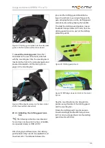
Page 33: ...ixing screws or one M6 axle fixing screw and a M6 nut 22 1 1 Replacing the caster wheels when mounted using two axle fixing screws To remove a caster wheel unscrew the M6 axle fixing screws AF 4 mm on...

Page 34: ...wheels when mounted using an axle fixing screw and nut To remove the caster wheel hold the M6 nut AF 10 mm firmly and loosen the M6 axle fixing screw AF 4 mm Now you can remove the M6 nut and washer t...

Page 35: ...t to overcome obstacles and makes tip ping necessary more often The smaller the caster wheel is the more driving skill is required Another way to reduce the fluttering is the use of a lighter caster w...

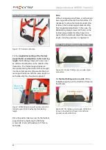
Page 36: ...ock must first be removed In order to release the cap you can run under the cap using a commercially available cutter knife and lift slightly at several points Then the M12 nut AF 19 mm is loosened us...

Page 37: ...r wheel axle again hold the caster wheel axle firmly and secure it with thread lock The nut of the caster wheel axle may not be tightened by more than 3 Nm to ensure it runs smoothly In case more slug...

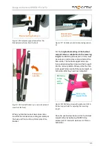
Page 38: ...with height adjustable slider on the front edge of the caster wheel bearing blocks The slider should be aligned at the middle of the caster wheel bearing block Information If the front edges of the ca...

Page 39: ...ay be nec essary to tilt the caster fork rotary axles from the vertical Chapter 22 4 23 Footrests Make sure the ground clearance under the footrest is sufficient Experience shows that this should not...

Page 40: ...fixing screws AF 4 mm with washers to 11 Nm on both sides Note With a V shaped product frame or with a larger lower leg width at the top than the bottom it is necessary to relieve the footrest suppor...

Page 41: ...M6 fixing screws AF 10 mm must be undone on both sides on the outside of the frame tube The footrest support tubes are then pushed along their slots and thus brought into the correct position Observe...

Page 42: ...in a vertical position to the footbar joint opened If the footrest should engage in the folded up position move the locking pin lever back to the horizontal position to the footbar joint The locking p...

Page 43: ...3 holes view without footrest support tube Once the M6 fixing screws AF 4 mm have been loosened on both sides move the foot rest support tubes so that the holes on both sides of the footrest support t...

Page 44: ...lower leg width at the top than the bottom and footrest support tubes that do not run parallel it is necessary to relieve the footrest support tube tension in the footrest support plate result ing fr...

Page 45: ...it into the operating position Figure 121 Moving the anti tipping support to oper ating position view from the rear Figure 122 Anti tipping support engaged correctly To move the anti tipping support...

Page 46: ...upport the anti tipping bar is inserted into the anti tipping sup port adapter from underneath and pulled up wards using the cord In doing so the M6 fixing screw must engage on the side of the footste...

Page 47: ...of the anti tipping support The following instructions are intended for and may only be carried out by a rehabilita tion specialist dealer or PRO ACTIV This must be removed first to adjust the height...

Page 48: ...r 24 1 2 24 2 Removable central anti tipping support Figure 132 Removable central anti tipping support view from the front 24 2 1 Removing and attaching the central anti tipping support The central an...

Page 49: ...hem first The lower edge of the anti tipping wheels may not be more than 5 cm from the ground If a larger gap is required or necessary then you need to work with your therapists and doctors to practic...

Page 50: ...ions are intended for and may only be carried out by a rehabilita tion specialist dealer or PRO ACTIV Settings on the brake could be necessary for the following reasons You have changed the tyre or th...

Page 51: ...int screws and M5 nuts For this purpose you need a slot ted screwdriver and an open ended span ner AF 8 mm The screw is held at the front with the slotted screwdriver and the open ended spanner AF 8 m...

Page 52: ...yre Figure 146 Brake opened closed by pushing the brake lever forwards and downwards Figure 147 Brake closed brake pin presses into the tyre by approx 4 mm Please note that the knee lever brake with p...

Page 53: ...attach the brake to the brake mounting bar on the brake mount Figure 149 M5 fixing screws Figure 150 Brake mount and brake mounting bar 3 Position the open brake so that there is approx 3 mm clearance...

Page 54: ...utwards until the brake element rests against the tyre Then press the control ele ment on the front part towards the tyre until the control element rests against the brake element and the brake notice...

Page 55: ...s You have changed the tyre or the tyre pressure You have changed the wheel tracking or the position of the drive wheels The brake is pulling unevenly or insuffi ciently after extended use To adjust t...

Page 56: ...pen if with the brake closed the tyre is depressed or deformed by approximately 4 mm by the brake ele ment at prescribed air pressure in the tyres 25 3 3 Brake adjustment for installation with welded...

Page 57: ...uct view from below Figure 165 Brake mount 3 Press the front part of the control element to the right or left outwards until the brake element rests against the tyre Do not close the brake completely...

Page 58: ...ck tubes To install the push handles place these in the back tube and insert the M6 fixing screws AF 4 mm with washers into the each of the holes of the back tube and push handle Tight en the M6 fixin...

Page 59: ...setting so that this does not protrude over the back tube to the side Video Safety push handles with con tinuous height adjustment https www youtube com watch v LFzGstT QvuI Figure 173 Put the clamp...

Page 60: ...ant to check that the handles are tightly fitted and fixed in position prior to use If this should no longer be the case then the push handles may not be used until they have been fixed 27 Passenger t...

Page 61: ...isting of 2 retractors at the front without hand tensioning wheel and 2 retractors at the rear with hand tensioning wheel e g manufacturer Schnierle Safety Belts GmbH Figure 176 Front retractor semi a...

Page 62: ...stem is fastened on one side of the product Figure 182 Symbol for front fastening and wheel chair loop at the front Figure 183 Symbol for rear fastening and wheel chair loop at the rear 27 5 Handling...

Page 63: ...ngle and connecting points view from the side The two rear belts must each be fastened symmetrically at a max angle of 10 outwards from the vertical Figure 187 Run of the retractors at the rear with m...

Page 64: ...p belt not to the latch plate provided in the vehicle Figure 189 Run of the lap and diagonal shoulder belt with the respective connecting points view from the front Adjustable inclination backrests mu...

Page 65: ...tion specialist dealer give it a general function and safety check 29 Transport 29 1 Securing handling of the product When loading or transporting the product can be held on the frame and on the back...

Page 66: ...product and have a firm grip on the back cross bar during the transport process 3 The second helper at the front grips the product by the frame and lifts the product up one step at a time 4 The helper...

Page 67: ...t PRO ACTIV 32 Maintenance 32 1 General instructions The product is not a maintenance free device Therefore please observe the following in structions about maintenance If repairs are required or ther...

Page 68: ...d six weeks after delivery The maintenance schedule can be found in the inspection lists in Chapter 40 Subsequent inspections are then always per formed a year after the last inspection The maintenanc...

Page 69: ...to your health insurance company or your rehabilita tion specialist dealer Your product can then be simply and economically re used Prior to each re use a technical safety check must be carried out on...

Page 70: ...and used in non compliance with these operat ing instructions Repairs or other work have been carried out by non authorised persons Third party parts have been installed or connected to the product o...

Page 71: ...ng clamps are present on the screw con nections or a lubrication instruction specifies the use of grease or copper paste In the following table you will find tools and care products for your PRO ACTIV...

Page 72: ...e also advised about situations where the assistance of another person is required The usage instructions were handed to me us Instructor Name date signature 1 Person being trained Name date signature...

Page 73: ...tended use as described in the usage instructions see Chapter Purpose and indication The product s equipment is suitable to allow the customer safe use with maximum reduction of risks The customer s d...

Page 74: ...s demonstrated and then tested by the user themselves and or their assis tant Adaptation of the wheelbase extension on the product if available was demonstrat ed and then performed by the user themsel...

Page 75: ...ion and safety check of the brakes push handles and anti tipping supports as well as further function assemblies such as e g folding backrest fold up footrest OK carried out OK not OK not OK resolved...

Page 76: ...re quired replace the tyres on the product Check that the wheel tracking and drive wheel bushing are firmly seated tightening torque 70 Nm Functional safety check of caster wheels Check the caster wh...

Page 77: ...e quired replace the tyres on the product Check that the wheel tracking and drive wheel bushing are firmly seated tightening torque 70 Nm Functional safety check of caster wheels Check the caster whee...

Page 78: ...re quired replace the tyres on the product Check that the wheel tracking and drive wheel bushing are firmly seated tightening torque 70 Nm Functional safety check of caster wheels Check the caster wh...

Page 79: ...e quired replace the tyres on the product Check that the wheel tracking and drive wheel bushing are firmly seated tightening torque 70 Nm Functional safety check of caster wheels Check the caster whee...

Page 80: ...re quired replace the tyres on the product Check that the wheel tracking and drive wheel bushing are firmly seated tightening torque 70 Nm Functional safety check of caster wheels Check the caster wh...

Page 81: ...e quired replace the tyres on the product Check that the wheel tracking and drive wheel bushing are firmly seated tightening torque 70 Nm Functional safety check of caster wheels Check the caster whee...

Page 82: ...re quired replace the tyres on the product Check that the wheel tracking and drive wheel bushing are firmly seated tightening torque 70 Nm Functional safety check of caster wheels Check the caster wh...

Page 83: ...e quired replace the tyres on the product Check that the wheel tracking and drive wheel bushing are firmly seated tightening torque 70 Nm Functional safety check of caster wheels Check the caster whee...

Page 84: ...n specialist dealer No 000 000 1653 05 2021 PRO ACTIV Reha Technik GmbH All rights reserved PRO ACTIV Reha Technik GmbH Im Hofst tt 11 D 72359 Dotternhausen Germany Phone 49 7427 9480 0 Fax 49 7427 94...

Reviews: