Usage instructions SPEEDY F4 and F2
55
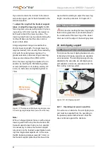
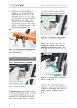
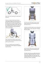
Figure 159: Brake element resting on the tyre
4. Move the integral brake on the hexagon
rail so that the brake element is positioned
as shown in the following figure:
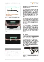
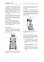
Figure 160: Brake element after correct
positioning of the integral brake
5. Tighten the M5 clamp screws (AF 4 mm) to
4 Nm again.
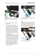
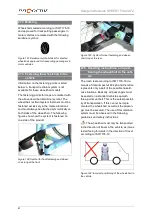
6. Then check the correct setting of the
brakes: On a slope (7° gradient) the prod-
uct should stand firm with the brake ap-
plied. This will happen if, with the brake
closed, the tyre is depressed or deformed
by approximately 4 mm by the brake ele-
ment (at prescribed air pressure in the
tyres).
25.3.3 Brake adjustment for installation
with welded-on bracket
The following instructions are intended
for and may only be carried out by a rehabilita-
tion specialist dealer or PRO ACTIV
The integrated brake on the SPEEDY F2 can
be fitted on the lower frame tube or on the
upper frame tube using a welded-on bracket.
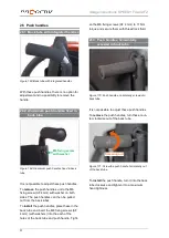
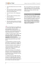
Figure 161: Fixing the integrated brake to the upper
frame tube
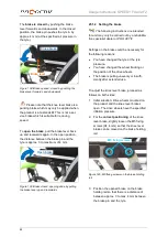
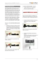
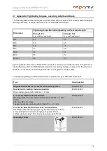
Figure 162: Fixing the integrated brake to the lower
frame tube
Figure 163: Fixing the integrated brake to the lower
frame tube
•
approx. 4 mm


