Usage instructions SPEEDY F4 and F2
41
Note:
With a V-shaped product frame or with a larger
lower leg width at the top than the bottom, it is
necessary to relieve the footrest support tube
tension in the footrest support plate resulting
from longitudinal adjustment or to correct the
shifted position of the footplate support. The
footplate support can be moved back to the
correct position by opening the M6 fastening
clamp screws (AF 5 mm) on the footrest sup-
port plate. View the procedure in Chapter 23.1.
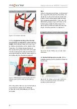
23.4 Footrest, fold up to the rear
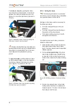
Figure 109: Footrest, fold up to the rear, in standard
position
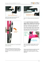
To
fold up the footrest to the rear
, move the
locking pin lever on the right and left side to the
vertical position to the footbar joints. Now you
can move the footrests to the rear.
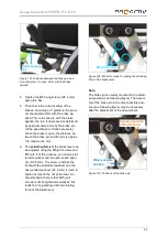
Figure 110: Locking pin lever in a vertical position to
the footbar joint, opened
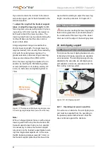
If the footrest should engage in the folded up
position, move the locking pin lever back to the
horizontal position to the footbar joint. The
locking pin levers are now not resting against
the footbar joints as the locking pins are not
engaged in the locking position yet.
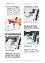
Figure 111: Locking pin lever in horizontal position,
not engaged and thus not resting against the footbar
joint
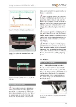
As soon as an engaged position is reached
during the return movement, the locking pins
engage and the levers rest against the footbar
joint.
Figure 112: Locking pin lever in horizontal position,
engaged and thus resting against the footbar joint
If you want to move the footrest back into the
standard position, perform the as previously
described and during this process, move the
footrest to the front.
Locking pin
lever in a
vertical
position
Fold-up to
the back
Locking pin
lever in
horizontal
position, not
engaged
Locking pin
lever in
horizontal
position,
engaged
Footbar joint


