ProActiv FREAK Operating Instructions Manual Download Page 26


                                                      Operating instructions NJ1 & FREAK Compact bike


25 


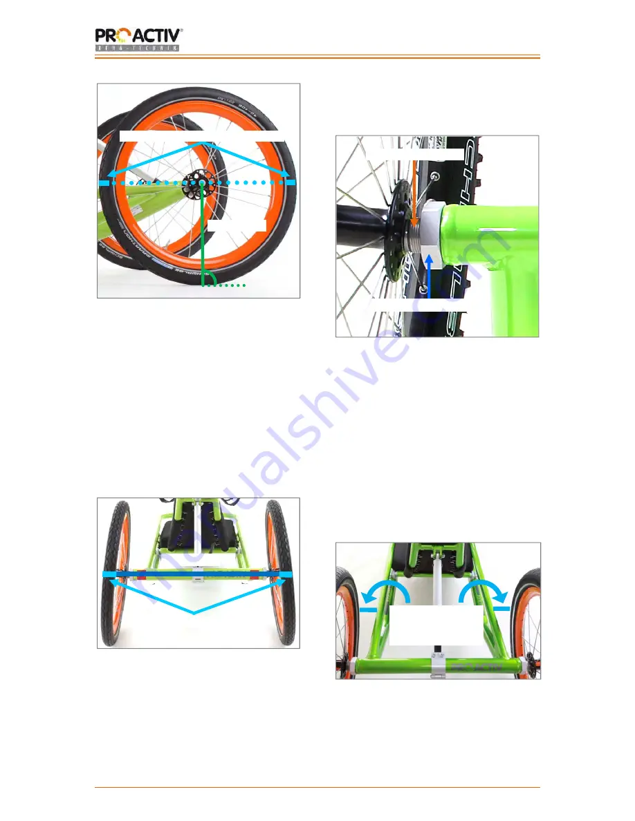
Figure 49: Drawing the axle height on the front and 
back of both tyres of the running wheels 


Afterwards measure the distance between the 
running wheels front and back at the height of 
the axles along the markers. Ideally, the 
distance between both running wheels should 
be the same size at the front and back. In 
general, it can be said that the distance 
between the running wheels at the front and 
back may not be larger 5 mm. If this is not the 
case, the wheel tracking needs to be 
corrected. 


Figure 50: Distance between the markers on the 
tyres (at axle height), back 


To 

adjust the track

 proceed as follows: 

1.  Loosen the aluminium locking nuts on both 

sides (AF 41 mm). 


Figure 51: Drive wheel bushing and aluminium, 
locking nut, product view from behind 


2.  Correctly adjust the track by turning the 

drive wheel bushing (AF 24 mm). Here it 
can be said that: If you turn the drive wheel 
bushing in the direction of travel, the track 
at the front will become more narrow. 
When turning against the direction of 
travel, the behaviour is exactly the 
opposite. 

3.  Make sure that the distance at the front to 

the frame on the right and left is the same. 


Figure 52: Distance at the front to the frame 


• 

Axle height 

Drawing the axle height onto tyres

Distance 

Markings 

Aluminium locking nuts 

Distance at front to 
frame the same 
size on both sides 

Drive wheel bushing 

Summary of Contents for FREAK

Page 1: ...Operating instructions NJ1 FREAK Compact bike 0 MOBILITY MADE SIMPLE Operating instructions Service booklet NJ1 Compact bike FREAK Compact bike...

Page 2: ...ent dimensions 6 8 5 Service life 7 9 Rating plate 7 10 Commissioning 7 11 Hand over 7 12 Safety instructions prior to driving use 8 13 Safety instructions while driving using 8 14 Safety instructions...

Page 3: ...on guard 23 20 1 Collision guard mount 23 20 2 Mounting the collision guard 23 20 3 Adjusting the length of the collision guard 24 21 Running wheels 24 21 1 Removing and attaching the running wheels 2...

Page 4: ...the chain shift 33 33 Appendix Tightening torques securing details and tools 34 34 Appendix Medical product passport record of training 35 35 Appendix Hand over certificate 36 35 1 Required complianc...

Page 5: ...rnings and safety instructions Serial number Additional information Assembly instructions for the dealer see table of contents 3 CE Declaration of Conformity other information 3 1 Classification The N...

Page 6: ...training of your arms Moreover the shoulder joints are relieved sufficiently compared with the usual propulsion of a wheelchair using the handrims In the medium term the body musculature is built up...

Page 7: ...permits the stop of the steering angle approx 4 m with manoeuvring highly dependent on the number of manoeuvres and has to how far the leg permits the stop of the steering angle 8 4 Basic equipment di...

Page 8: ...ating instructions and any other accessories for your own use The form for the record of training and the hand over certificate can be found in chapters 34 and 35 It is recommended that you take along...

Page 9: ...y and must not be covered by other objects Especially trips that take place in the dark or in the twilight the lighting must be functional and visible For longer trips in the dark we recommend that yo...

Page 10: ...If the situation allows it the speed should be reduced by carefully applying the service brake Abrupt braking can cause the upper body to fall forwards which can thereby result in injuries or loss of...

Page 11: ...of gravity Always perform these driving manoeuvres with increased caution and only at slow speed If required the driving manoeuvre must not be performed or only with the help of an assistant When cro...

Page 12: ...s point completely forward away from the body and the shoulders should rest against the backrest 16 1 2 Pedal bearing position When equipping the product with a pedal bearing support that cannot be ad...

Page 13: ...M6 fixing screws for angle and height adjustment of the pedal bearing position If you want to make a change to the pedal bearing position please contact your dealer or PRO ACTIV Please note that after...

Page 14: ...the next largest sprocket means a lower or easier gear and to the next smallest sprocket to a larger or more difficult gear For the 3 speed chain wheels at the top the behaviour is exactly the opposit...

Page 15: ...ears as the efficiency and service life of the chain will fall significantly more information can be found in chapter 32 For more information please see the instructions provided by the gear manufactu...

Page 16: ...r alternatively can also be operated with the thumb by pressing against the direction of travel The index finger switch is operated for switching up and the thumb switch is operated for switching down...

Page 17: ...he charger when the orange lamp goes out is pushed back along the retaining rail until you can feel a slight resistance When closing the flap on the side the rechargeable battery is completely secured...

Page 18: ...lever In the event of abrupt hard braking there is a risk that you might fall forward with your upper body and thereby cause injuries to yourself Please make sure that the braking surfaces on the rim...

Page 19: ...n be operated from the operating lever opened 16 5 PRO ACTIV back pedal brake crank release function 16 5 1 Operation The PRO ACTIV back pedal brake can be used for chain gears or hub drives with a fr...

Page 20: ...ease function the left hand pressure plate must be operated seen from the direction of travel To return to normal driving operation with the back pedal brake the right hand pressure plate must be oper...

Page 21: ...w sigmasport com Subject to changes to the links provided by the component manufacturers 17 Backrest 17 1 Angle adjustment of the backrest For adjusting the angle of the backrest open the clamp lever...

Page 22: ...ased The clamps on the right and left side must be positioned at the same height of the product frame Figure 35 Longitudinal adjustment of the backrest via M6 fixing screws and clamps on the frame of...

Page 23: ...oreover the seat cushion also ensures for equal pressure distribution 19 Neck rest 19 1 Neck rest height adjustment To adjust the height of the neck rest two M6 fixing screws AF 5 mm have be loosened...

Page 24: ...done on the right and left inlet Now the collision guard can be removed from the inlet Figure 43 M6 fixing screws on the clamp on the axle tube 20 2 Mounting the collision guard Figure 44 Inlet of the...

Page 25: ...ers By pressing the locking knob in the middle of the wheel axle with your thumb the wheels can then easily be removed When attaching the running wheels the locking knob also has to be pressed Special...

Page 26: ...at axle height back To adjust the track proceed as follows 1 Loosen the aluminium locking nuts on both sides AF 41 mm Figure 51 Drive wheel bushing and aluminium locking nut product view from behind 2...

Page 27: ...at surfaces 22 2 Terminology The product comprises drive unit and product frame The product frame is also designated as chassis The insertion shaft is located on the adapter plate of the chassis Figur...

Page 28: ...and chassis can completely rest on top of one another In doing so make sure that the insertion maul and the insertion shaft stay in position Figure 59 Adapter plates of the drive unit and chassis res...

Page 29: ...e eccentric pin is removed from the adapter plates For easier handling raise the drive unit on the pedal bearing housing slightly in the process After removing the eccentric pin the chassis is lowered...

Page 30: ...rt so that they are not damaged e g by falling over and do not become a hazard to persons or other products When loading make sure that the cables and lines are not caught up become kinked or otherwis...

Page 31: ...arcass or the puncture proofing is visible on the product the tyres must be changed as otherwise there is an increased risk of an accident When maintaining the brakes and the gear components it is imp...

Page 32: ...ce reports as a means of proof and get any service work which was not carried out by PRO ACTIV documented Please bring these operating instructions service booklet to every service 28 Disposal Recycli...

Page 33: ...res 24 months after the product was delivered Further information can be found in PRO ACTIV s general terms and conditions at www proactiv gmbh com Any modifications to the product which have not been...

Page 34: ...itch to all 9 sprockets from the large chain wheel you can switch to the small sprockets 1 7 from the large chain wheel you should not switch to the large sprockets 8 9 crossed gear from the small cha...

Page 35: ...s on PRO ACTIV products should be secured with thread lock fluid medium strength e g Weicon AN302 42 where there are no securing clamps on the screw connections present or there is a lubrication requi...

Page 36: ...lso advised about situations where the assistance of another person is required The operating instructions were handed to me us Instructor Name date signature 1 Person being trained Name date signatur...

Page 37: ...ulations in accordance with the road traffic regulations The customer s driving ability was checked during a test drive in difficult driving situations and found to be appropriate see the check list o...

Page 38: ...tant Removal and installation of the running wheels was demonstrated and then tested by the user themselves and or their assistant Test drive Forwards and if required backwards travel through 4 cones...

Page 39: ...ional and safety check of all lights if fitted steering and adaptation of the drive unit to the chassis Functional and safety check of the brakes and where necessary replacement of the brake fluid bra...

Page 40: ...ning and oiling the gear components including pedal bearing gearshift if fitted Check the spoke tension of the drive wheel and if required correct the tension re centring Functional and safety check o...

Page 41: ...ning and oiling the gear components including pedal bearing gearshift if fitted Check the spoke tension of the drive wheel and if required correct the tension re centring Functional and safety check o...

Page 42: ...ning and oiling the gear components including pedal bearing gearshift if fitted Check the spoke tension of the drive wheel and if required correct the tension re centring Functional and safety check o...

Page 43: ...ning and oiling the gear components including pedal bearing gearshift if fitted Check the spoke tension of the drive wheel and if required correct the tension re centring Functional and safety check o...

Page 44: ...ning and oiling the gear components including pedal bearing gearshift if fitted Check the spoke tension of the drive wheel and if required correct the tension re centring Functional and safety check o...

Page 45: ...ning and oiling the gear components including pedal bearing gearshift if fitted Check the spoke tension of the drive wheel and if required correct the tension re centring Functional and safety check o...

Page 46: ...ning and oiling the gear components including pedal bearing gearshift if fitted Check the spoke tension of the drive wheel and if required correct the tension re centring Functional and safety check o...

Page 47: ...ning and oiling the gear components including pedal bearing gearshift if fitted Check the spoke tension of the drive wheel and if required correct the tension re centring Functional and safety check o...

Page 48: ...eha Technik GmbH Im Hofst tt 11 72359 Dotternhausen Germany Tel 49 7427 9480 0 Fax 49 7427 9480 7025 E Mail info proactiv gmbh de www proactiv gmbh com No 000 000 1522 11 2014 PRO ACTIV Reha Technik G...

Reviews: