13
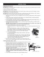
5. Position yourself and the free end of the cable (attached to the NEG battery terminal) as far away from
the battery as the cable will allow. Then, WHILE FACING AWAY FROM THE BATTERY, connect the
NEGATIVE charger clamp to the free end of the cable.
6. When disconnecting charger, turn switches to off, disconnect AC cord and disconnect charger, always
in reverse sequence of connecting procedure and break first connection while as far away from battery
as practical.
Charging Mode Operation
ATTENTION: Do not plug the charger power cord into the AC power source or set any of the charger’s controls
until told to do so in the following instructions.
ATTENTION: Connect and disconnect DC output clamps only after setting the power switch to the “OFF”
position and unplugging the AC cord from electric outlet. Never allow clamps to touch each other.
ATTENTION: Do not operate the charger in a closed area or restrict ventilation in any way. Ensure that there that
there are no obstructions to the air flow, so the internal fans can properly cool the unit.
Make a proper battery connection (see Connecting to a Battery Sections as applicable) and plug AC power cord
into an AC receptacle. Then, turn the master power switch to ON. The charger is now in Standby Mode.
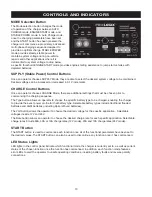
In order to place the unit into Charging Mode, toggle the Mode Selection button until the CHARGE LED is lit. If an
ERROR Indicator LED lights, disconnect from AC stable power immediately and determine the cause of the alarm.
The POLARITY light indicates reverse polarity error connection, while the ERROR light indicates the detection of a
battery fault, such as a shorted connection.
1. Choose a battery type setting. To charge Standard and Maintenance Free Flooded Acid batteries, push the
Battery Type button until the “STD” LED is lit. To charge AGM and Spiral Wound batteries, push the Battery
Type button until the “AGM” LED is lit.
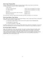
2. Choose a battery charging rate. Please see Choosing a Charge Rate section for general details related to
choosing a charging rate for your application.
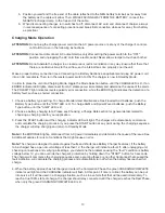
3. Press the START button and the charging indicator LED will light. The charger will automatically commence
and complete the charging process. If you press the START button at any point during the charging sequence,
the charger will stop charging and return to Standby Mode.
Note: If the ERROR LED lights, disconnect from AC power immediately and determine the cause of the issue. See
Additional Features for a list of conditions that might cause an error.
Note: The charger is designed to protect against faults and shorts (see Battery Charger Features). If the battery
to be charged has a open circuit voltage of less than 1V, the charger will indicate a fault. If, after unplugging unit,
checking connections and verifying all settings, you determine the problem causing the “fault” condition is battery
voltage below 1V, you can override the charger’s protection by holding down the “START” button for 3 seconds.
The charger will commence the charging sequence and, assuming these are no other hindrances that caused the
fault indication, will complete the charging process and automatically turn off when the battery has reached full
charge.
4. When the battery approaches full charge and enters the Completion Phase, the green CHARGING COMPLETE
indicator will light and the CHARGING indicator will flash. At this point, if time is critical, the battery can be put
into service if it will be used in a charging situation, such as in a vehicle that that will be used immediately. To
reach a true 100% state of charge, the charger should stay connected until the charger reaches the Rest Phase,
when only the green CHARGING COMPLETE LED is lit.

