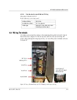
GTIB-30 Installation Manual-UL
4411-0011, Rev 2.0
45
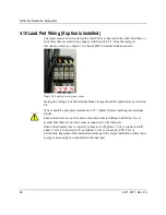
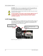
4.7 Earth Wiring
It is essential that the GTIB-30 is connected to protective earth ground of the premises.
The GTIB-30 provides a special terminal for this connection (see Figure 20). Once
this terminal is earthed, the internal wiring of the GTIB-30 will ensure that all parts
of the enclosure and other touchable metal parts are properly shorted to the protective
earth ground.
It is the responsibility of the installer to ensure that all grounding arrangements
are NEC compliant before proceeding with the installation. PPS takes no
responsibility for damage or injuries resulting from non NEC compliant
grounding arrangements.
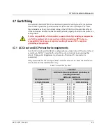
4.7.1 AC Circuit and DC Port earth wire requirements
For the AC circuits and the Battery configuration, a ground wire will be sized at least
according to Table 7, based on the size of the over-current device protecting that
circuit. Voltage and temperature requirements of Section 4.5.1 must also be
considered.
The ground wire for the PV input will be rated for at least 1.25 times the rated short-
circuit current of the installed PV array.
Table 7: Ground Wire Size Chart
Column 1
Column 2
Minimum size of equipment grounding or
bonding conductor
AWG or kcmil (mm)
Maximum current
rating in Amperes
Copper
Aluminum or copper-
clad aluminum
15
14
(2.1)
12
(3.3)
20
12
(3.3)
10
(5.3)
30
10
(5.3)
8
(8.4)
40
10
(5.3)
8
(8.4)
60
10
(5.3)
8
(8.4)
90
8
(8.4)
6
(13.3)
100
8
(8.4)
6
(13.3)
150
6
(13.3)
4
(21.2)
Summary of Contents for GTIB-30
Page 1: ...Clean power made simple GTIB 30 Installation Manual ...
Page 2: ...www princetonpower com 4411 0011 Rev 2 0 April 1st 2014 ...
Page 11: ...About this Manual 4411 0011 Rev 2 0 xi This page intentionally left blank ...
Page 15: ...Contents 4411 0011 Rev 2 0 15 This page intentionally left blank ...
Page 16: ...1 Introduction ...
Page 18: ...2 System Overview and Configurations ...
Page 31: ...3 Pre Installation ...
Page 36: ...GTIB 30 Installation Manual UL 36 4411 0011 Rev 2 0 This page intentionally left blank ...
Page 37: ...4 Wiring Instructions ...
Page 56: ...GTIB 30 Installation Manual UL 56 4411 0011 Rev 2 0 This page intentionally left blank ...
Page 57: ...5 Commissioning Sequences ...
Page 61: ...GTIB 30 Installation Manual UL 4411 0011 Rev 2 0 61 This page intentionally left blank ...
Page 62: ...A GTIB 30 kW Specifications ...
Page 65: ...GTIB 30 Installation Manual UL 4411 0011 Rev 2 0 65 This page intentionally left blank ...
Page 66: ...B Return Material Authorization Contact and Product Information ...
Page 69: ...GTIB 30 Installation Manual UL 4411 0011 Rev 2 0 69 This page intentionally left blank ...


