GTIB-30 Installation Manual-UL
4411-0011, Rev 2.0
25
2.1.4.6
Integrated DC Switch
The GTIB-30
’s integrated battery
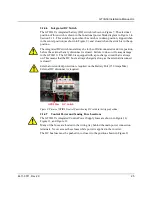
(DC) switch is shown in Figure 7. The electrical
position of this switch is shown in the functional power block diagram in Figure 3 in
Section 2.1.3. This switch is open when the switch is in down position, tripped when
in the center position (as shown in Figure 9), and closed when the switch is in the up
position.
The integrated DC switch must always be in the off (disconnected or down) position
before the external battery disconnect is closed. Failure to do so will cause damage
to the GTIB-30. The GTIB-30 is equipped with a pre-charge circuit that is always
on. This means that the DC bus is always charged as long as the external disconnect
is closed!
External overcurrent protection is required on the Battery Port (150 Amps Max).
External DC disconnect is required.
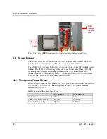
Figure 9: Picture of GTIB-30 control Panel showing DC switch in the tripped position.
2.1.4.7
Control Power and Sensing Fuse Locations
The GTIB-30
’s integrated Control Power
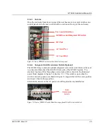
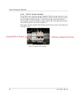
Supply fuses are shown in Figure 10,
Figure 11, and Figure 12.
Many of the fuses are located in the wiring tray behind the main power connection
terminals. Never access these fuses while power is applied to the inverter.
The DC bus fuse must be pushed in to close it to the position shown in Figure 11.
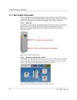
DC Switch
GFDI Fuse
Summary of Contents for GTIB-30
Page 1: ...Clean power made simple GTIB 30 Installation Manual ...
Page 2: ...www princetonpower com 4411 0011 Rev 2 0 April 1st 2014 ...
Page 11: ...About this Manual 4411 0011 Rev 2 0 xi This page intentionally left blank ...
Page 15: ...Contents 4411 0011 Rev 2 0 15 This page intentionally left blank ...
Page 16: ...1 Introduction ...
Page 18: ...2 System Overview and Configurations ...
Page 31: ...3 Pre Installation ...
Page 36: ...GTIB 30 Installation Manual UL 36 4411 0011 Rev 2 0 This page intentionally left blank ...
Page 37: ...4 Wiring Instructions ...
Page 56: ...GTIB 30 Installation Manual UL 56 4411 0011 Rev 2 0 This page intentionally left blank ...
Page 57: ...5 Commissioning Sequences ...
Page 61: ...GTIB 30 Installation Manual UL 4411 0011 Rev 2 0 61 This page intentionally left blank ...
Page 62: ...A GTIB 30 kW Specifications ...
Page 65: ...GTIB 30 Installation Manual UL 4411 0011 Rev 2 0 65 This page intentionally left blank ...
Page 66: ...B Return Material Authorization Contact and Product Information ...
Page 69: ...GTIB 30 Installation Manual UL 4411 0011 Rev 2 0 69 This page intentionally left blank ...


