GTIB-30 Installation Manual-UL
4411-0011, Rev 2.0
39
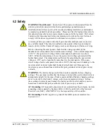
4.2 Safety
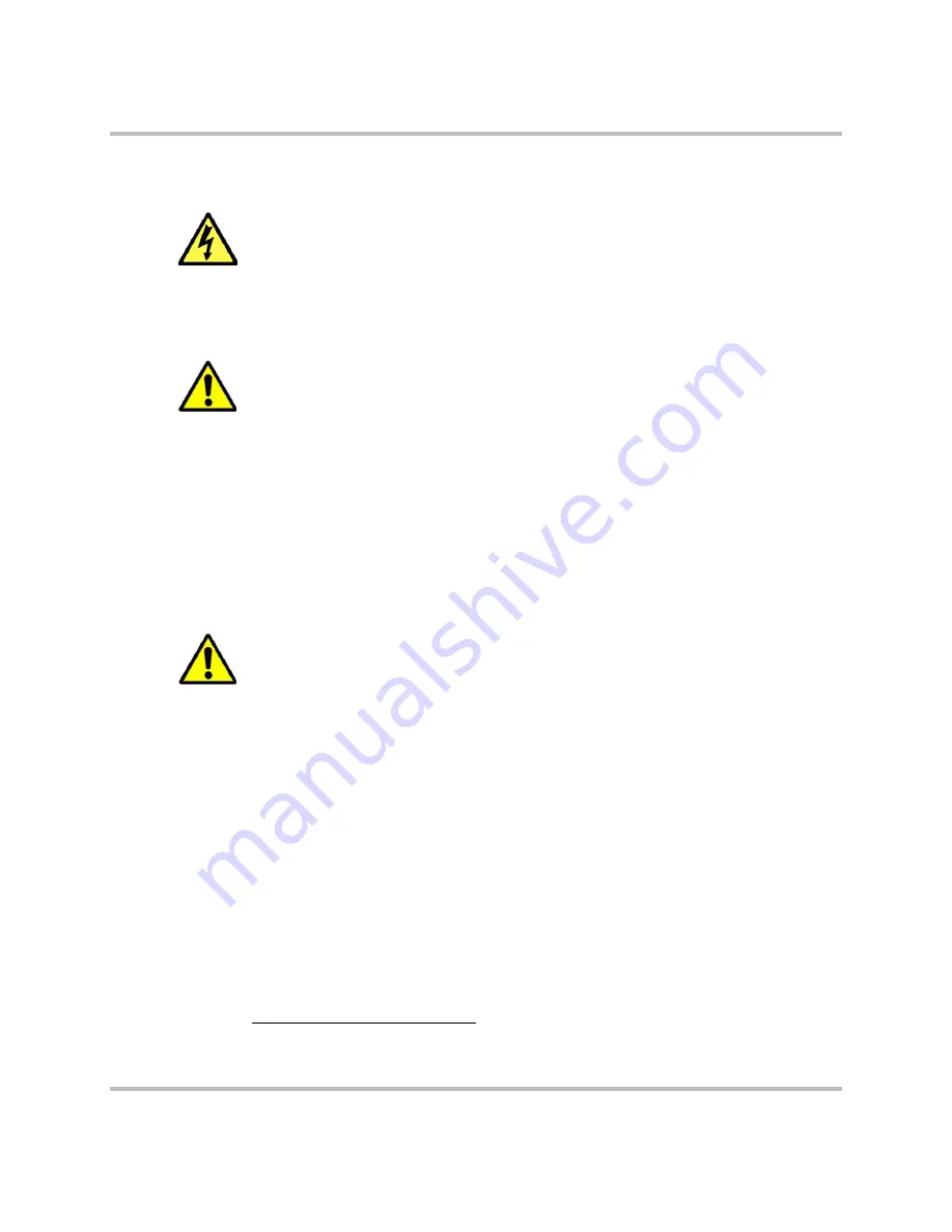
WARNING: Shock Hazard:
Ensure that all three ports are disconnected from the
unit via external disconnect switches before performing any maintenance or
installation. Ensure that no port can be reconnected during installation or maintenance
by employing standard lock out procedures. Please note that the load port must also be
disconnected since other power sources might connected to the load port. Wait at least
5 minutes after disconnection before commencing with work on the unit. Failure to
comply with the above requirements could cause serious injury or death.
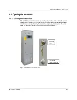
A warning label is provided to inform all personnel that multiple sources of power
are available inside. This label is installed on the outside of the door and should
remain clearly visible. Ensure all energy sources are disconnected before servicing.
Before connecting the solar panels, check that the voltage specified by the
manufacturer corresponds to the actual measured voltage. At an outside temperature
of -10°C
1
, the open-circuit voltage for the solar panels should never rise above
600 V. When the temperature is lower, the open-circuit voltage generated will be
higher than normal. The temperature coefficients for calculating the open-circuit
voltage at -10°C can be found in the data sheet for the solar panels. If the open-
circuit voltage for the solar panels rises above 600 V, this may result in damage to the
inverter and all warranty rights shall be declared null and void. Damage to the
inverter may cause a hazardous condition that puts personnel at risk of grave injury
or death.
WARNING:
The battery charge control function has adjustable battery charging
settings. The user must confirm that the charge control profile used in this inverter is
appropriate and safe for the type of battery used and that all battery charging settings
are set correctly for the battery voltage, current, and temperature ratings. Setting
these settings incorrectly may damage the battery and the inverter and may cause a
hazardous condition that puts personnel at risk of grave injury or death.
AC Grounding:
All input and output circuits are isolated from the enclosure. System
grounding, when required by Sections 690.41, 690.42, and 690.43 of the National
Electric Code (NEC), ANSI/NFPA 70, is the responsibility of the installer.
DC Grounding:
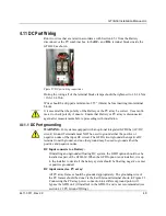
The DC negative is ground if the GFDI option is installed. See
Section 4.11.1.
1
In extreme locations, it might be necessary to use even lower temperature value. Contact Princeton
Power System if you are using a PV system in extremely cold but sunny conditions.
Summary of Contents for GTIB-30
Page 1: ...Clean power made simple GTIB 30 Installation Manual ...
Page 2: ...www princetonpower com 4411 0011 Rev 2 0 April 1st 2014 ...
Page 11: ...About this Manual 4411 0011 Rev 2 0 xi This page intentionally left blank ...
Page 15: ...Contents 4411 0011 Rev 2 0 15 This page intentionally left blank ...
Page 16: ...1 Introduction ...
Page 18: ...2 System Overview and Configurations ...
Page 31: ...3 Pre Installation ...
Page 36: ...GTIB 30 Installation Manual UL 36 4411 0011 Rev 2 0 This page intentionally left blank ...
Page 37: ...4 Wiring Instructions ...
Page 56: ...GTIB 30 Installation Manual UL 56 4411 0011 Rev 2 0 This page intentionally left blank ...
Page 57: ...5 Commissioning Sequences ...
Page 61: ...GTIB 30 Installation Manual UL 4411 0011 Rev 2 0 61 This page intentionally left blank ...
Page 62: ...A GTIB 30 kW Specifications ...
Page 65: ...GTIB 30 Installation Manual UL 4411 0011 Rev 2 0 65 This page intentionally left blank ...
Page 66: ...B Return Material Authorization Contact and Product Information ...
Page 69: ...GTIB 30 Installation Manual UL 4411 0011 Rev 2 0 69 This page intentionally left blank ...

