


15
Function Descriptions
Counters
NOTE: All counters are automatically stored at
power down.
The PressCam 8 provides four types of counters: Stroke,
Batch, Quality, and Part. When programmed properly a
counter will increment each time a part is ejected from
the machine. When the programmed value is met, the
controller will initiate an action.
Stroke Count.
The Stroke Counter is used to indicate
the total number of strokes that has occurred since the
last stroke counter reset. This number increases by
one every time the resolver passes 340° regardless of
job changes or faults. You can reset this count in RUN
or PROG modes.
Part Count.
This box has two
fi
elds—In the upper right,
a
Part Increment
fi
eld which represents the number of
parts produced per stroke, and a
Part Count
fi
eld which
shows the number of parts produced. You can only set
the
Part Increment
fi
eld in PROG mode.
The programmer can set the number of how many parts
are being counted or produced on each stroke of the
press. They can set the unit to count 0 through 4. If the
unit is set to zero, then the PressCam 8 will not increment
the Part Count, Batch Count or the Quality Count.
You can reset the
Part Count
in RUN or PROG modes.
NOTE: The Part count automatically increments
off the Stroke count, unless DIE #7 is activated as
a “Momentary” die type with different “Begin” and
“End” angles. In this case, you will need to provide a
sensor input to DIE #7 to increment the Part count.
The Part Increment
fi
eld is used by the Batch and Quality
counters. Resetting the Part Counter will not affect the
other counters.
Batch Size.
The Batch Size determines when the Batch
Count increments. This can only be changed in PROG
mode. The Batch Size is based on the Part Increment
fi
eld size (the upper right of the Part counter box)
Batch Count.
The Batch Counter is used to indicate the
number of batches completed and/or stop the machine
when a batch is complete (using Output Relay #12).
This can be reset in RUN or PROG modes.
NOTE: Batch Counter only works when Part Count
is wired to a sensor and is activated.
Quality Count.
The Quality Counter is used to stop the
machine when the parts produced reaches the value
in the “Quality Count”. This is used to indicate to the
operator that the last part should be checked for quality
purposes based on your company’s SPC requirements.
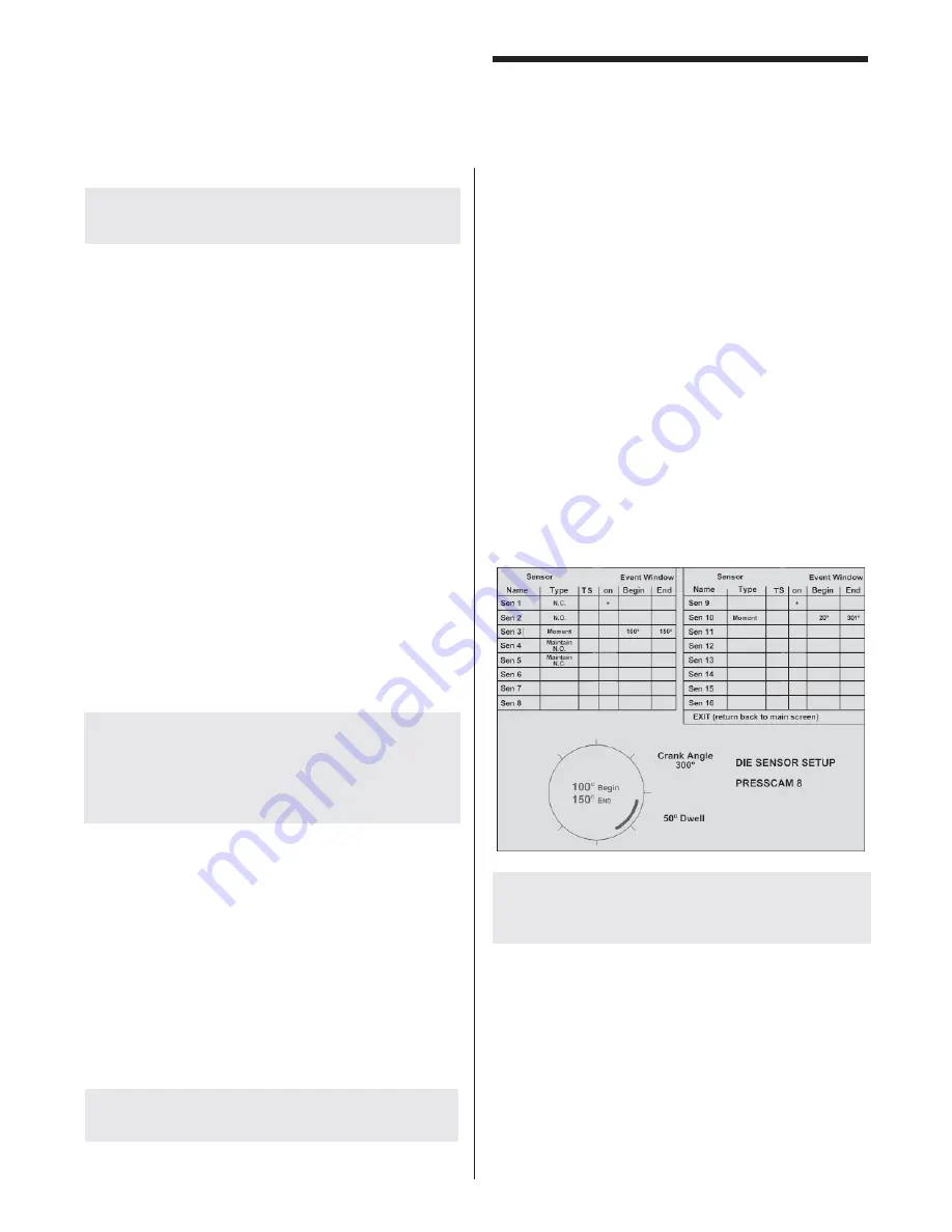
Die Sensor Setup
This function is used by the programmer to program any
one of the sixteen die protection inputs and can only be
highlighted and accessed in the PROG mode.
Die Sensor Inputs 1 to 16 can have custom selected
names. The names can only be changed while in PROG
mode (refer to the “Job Selection” section for details
on how to enter in names). If Sensor #7 is setup for
“Momentary” and has a valid angle window, the computer
will use this input to increment the Parts Counter. This
is why the default name is “Part Cnt.”
To change the name of a Die Sensor Input, refer to “Job
Selection” section.
NOTE: In PROG mode, the PressCam 8 will not
shut down on a die fault but will limit you to ten
cycles.
Main Screen Die Sensor Display
When a die sensor input faults an “f” is indicated. When
in the die window the faulted sensor shows “F”.
A faulted sensor also shows the last CLOSE-OPEN
angles seen by the computer, to help determine if and
where the sensor changed states.
If the sensor faults, but the angles shown are within the
die settings, then the sensor did not change states the
last cycle.
Summary of Contents for PressCam 8
Page 1: ...PressCam 8 Installation Operations Manual ...
Page 2: ...Rev 5 0 ...
Page 14: ...6 Internal Wiring Diagram 28 101 System Installation ...
Page 15: ...7 Control Box Dimensions 28 102 System Installation ...
Page 16: ...8 Panel Cut Out Dimensions 28 103 System Installation ...
Page 17: ...9 Control Panel Dimensions 28 104 System Installation ...
Page 18: ...10 System Installation External Wiring Diagram 28 105 ...
Page 19: ...11 System Installation I O Board Dimensions 28 106 ...
Page 44: ...36 Tonnage Load Monitor optional Installation T400 Installation ...