background image


Inhoudsopgave 

1


INTRODUCTION ............................................................................................................................................................. 4


T

HE 

G

OALS OF THE INSTALLATION

 ................................................................................................................................. 4


R

EDUNDANCY

 ......................................................................................................................................................... 4


2


PRECAUTIONS AND SAFETY INSTRUCTIONS FOR NITROGEN GENERATORS .................................................................... 5


G

ENERAL SAFETY STANDARDS

 ...................................................................................................................................... 5


W

ORKING WITH THE NITROGEN GENERATOR

.................................................................................................................... 5


D

ESCRIPTION OF HAZARD SYMBOLS

 ............................................................................................................................... 5


3


THE LOX INSTALLATION ................................................................................................................................................. 7


T

HE 

LOX

 SYSTEM BASICS

 ........................................................................................................................................... 7


S

YSTEM DESCRIPTION

 ................................................................................................................................................ 9


Compressor ............................................................................................................................................................ 9 


Compressed air conditioning ................................................................................................................................. 9 


Nitrogen generator ................................................................................................................................................ 9 


LOX opstelling ...................................................................................................................................................... 10 


Nitrogen inlet ....................................................................................................................................................... 10 


N

2

 Control ............................................................................................................................................................ 11 


Ox Control ............................................................................................................................................................ 11 


Oxygen sensors .................................................................................................................................................... 11 


Informing and alerting ......................................................................................................................................... 12 


The Color Display ................................................................................................................................................. 12 


Emergency stop ................................................................................................................................................... 13 


Humidity sensor ................................................................................................................................................... 13 

4


BEDIENING VAN DE INSTALLATIE ....................................................................... 

FOUT! BLADWIJZER NIET GEDEFINIEERD. 


ECD


D

ISPLAY

 ....................................................................................................................................................... 14


ECD Display front ................................................................................................................................................. 14 


Buttons on the ECD Display ................................................................................................................................. 14 


Button functionality ............................................................................................................................................. 15 


Status LED’s

 ......................................................................................................................................................... 17 

5


ASSEMBLY INSTRUCTIONS ........................................................................................................................................... 18


6


MEASURES DURING DECOMMISSIONING .................................................................................................................... 18


7


ERRORS ....................................................................................................................................................................... 19


E

RRORLEVELS

 ........................................................................................................................................................ 19


Error messages in general .................................................................................................................................... 20 


Error messages from the N

2

 Control .................................................................................................................... 24 


Error messages from the ECD Display .................................................................................................................. 28 


Error messages from the Ox Control ................................................................................................................... 32 


Error messages from the FX Connect................................................................................................................... 36 


T

ROUBLESHOOTING

 ................................................................................................................................................ 40


Reaction times ..................................................................................................................................................... 40 

8


MAINTENANCE ............................................................................................................................................................ 41


FX


P

REVENT

 ......................................................................................................................................................... 41


Compressor .......................................................................................................................................................... 41 


LOX system .......................................................................................................................................................... 41 


Oxygen sensors .................................................................................................................................................... 41 


Pressure Equipment, examination of commissioning and reinspection during using phase ............................... 42 


M

AINTENANCE CONTRACT

 ........................................................................................................................................ 42


9


APPENDIX .................................................................................................................................................................... 43


10


DOCUMENT HISTORY .................................................................................................................................................. 43


11


TO CONCLUDE ............................................................................................................................................................. 44


Summary of Contents for LOX

Page 1: ...LOX Low Oxygen System User Manual Type User manual Date 21 januari 2021 Version Revision Version 4 0 Revision 00 Status Approved Company PRESSCON FX Prevent Location Honselersdijk ...

Page 2: ...2 ...

Page 3: ...ensor 13 4 BEDIENING VAN DE INSTALLATIE FOUT BLADWIJZER NIET GEDEFINIEERD ECD DISPLAY 14 ECD Display front 14 Buttons on the ECD Display 14 Button functionality 15 Status LED s 17 5 ASSEMBLY INSTRUCTIONS 18 6 MEASURES DURING DECOMMISSIONING 18 7 ERRORS 19 ERRORLEVELS 19 Error messages in general 20 Error messages from the N2 Control 24 Error messages from the ECD Display 28 Error messages from the...

Page 4: ...ating parameters These may only be changed by FX Prevent or its authorized party The operating pressure of the installation is between 0 and 8 bar The design pressure is 10 bar This pressure may not be exceeded under any circumstances The temperature of the room where the system is installed should be no lower than 3 C and no higher than 40 C Redundancy The LOX system like all other technical inst...

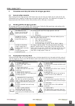
Page 5: ...output connection may cause intoxication The nitrogen quickly mixes with the ambient air so that at a distance of 0 5m from the nitrogen output connection it no longer poses a health risk Description of hazard symbols In addition to the identified risks for the nitrogen generator the following symbols can also be applied within the system of which the nitrogen generator is part of When a hazard sy...

Page 6: ...to the nitrogen generator please refer to the enclosed instructions of those components that are provided by the respected manufacturers These can be found with the specific components upon delivery or are included within the technical file of system of which the nitrogen generator is part of ...

Page 7: ...hing light Acoustic alarm slowwhoop evacuation alarm Door display at each access door Communication equipment for communication with the supplier s failure department Electrical cabling for the control centre s oxygen measuring equipment alarm detectors and access control equipment The LOX oxygen reduction system serves a maximum of 24 rooms The following components are installed in each of these ...

Page 8: ...8 Figure 1 Schematic setup of the LOX system basics ...

Page 9: ... the compressed air supply this will lead to damage to the nitrogen generators of the installation FX Prevent has taken measures to permanently monitor the quality of the compressed air by using a moisture detection sensor The compressed air conditioning section consists of the following components depending on the installation Water separator per compressor Compressed air buffer tank Oil and wate...

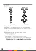
Page 10: ...egulated by means of valves The supply of nitrogen is automatically controlled via the LOX control software and is not described separately in this manual LOX controller The LOX controller is the nerve center of the installation The basic functions of the controller are the control of the nitrogen production units taking care of the communication between the various components registering and corr...

Page 11: ...itor deviations If the oxygen level becomes too high or too low the Ox Control generates an error or alarm message that is visible on the ECD display and indicated by a flashing light and or a slow whoop The Ox Control also checks the status of the power supply The Ox Controls installed as a leading or redundant controller are not different from each other and are always constructed in the same wa...

Page 12: ...ess doors are kept closed as much as possible To register the use of the access doors and to warn the people present if a door is left open it is optional to equip these with door contacts If a door is left open for longer than the set time an alarm will activate The door switch monitoring is part of the LOX system and is therefore not described separately in this guide It is operated via the LOX ...

Page 13: ...an be stopped by pressing the emergency stop button once When the user does this the following will happen The power supply to the LOX nitrogen generator is interrupted The power supply to the compressors for the LOX system is interrupted The LOX Control panels Oxysensors Color Displays and the nitrogen generator switch to the Uninterrupted Power Supply UPS These components are supplied with power...

Page 14: ...of the ECD display The display and the columns of LEDs are both part of the PCB Info Prog Esc Alarm Reset Netherlands Power ok Alarm Fault Disabled Transmission path fault Nitrogen generator fault N2 production active O2 level minimum O2 level maximum Power supply fault Program fault Figure 8 ECD Display Buttons on the ECD Display Reset button The reset button is used for restoring the LOX Control...

Page 15: ...erator menu and Factory menu are mentioned These three menus are basically the same but are renamed and expanded each time that the user is logged in into a higher access level via the ECD display The higher the access level gets the more settings become available in this menu Button Action Description Reset Pressed shortly Only the internal buzzer of the ECD display is silenced Held down If the u...

Page 16: ...dary action is programmed Pressed shortly At the main screen The Guest menu Operator menu or Factory menu is accessed and the first line of that menu is selected directly At the Guest Operator Factory menu or a sub menu Press this button once the select the next menu screen When adjusting a setting Press this button once the increase a value or to select the next possible setting during adjustment...

Page 17: ...LED is on then the oxygen level has become higher than the maximum allowed concentration This means that the prevention of fire by oxygen reduction is no longer guaranteed Disabled If this LED is on then there has been one or more inputs or outputs manually disabled Once there are no more inputs or outputs disabled then this LED is off Power supply fault If this LED is on then the main power suppl...

Page 18: ...s necessary to avoid a fire hazardous atmosphere The assembly and positioning of the components of the LOX system must be in accordance with the pre fabricated installation drawing The installation drawing is worked out specifically for each system and is available in the technical file of the system Part of the connections between the components can be fixed pipe connections Fixed pipe connection...

Page 19: ...error or alarm Errorlevels These warnings and fatal errors are subdivided into 4 error levels How the system reacts and which outputs are controlled depends on the error level Error Level Message Responds of the system 1 Warning Warning is shown on the display The alarm relay of the N2 or OX controller reacts 2 Warning Warning is shown on the display The alarm relay of the N2 or OX controller reac...

Page 20: ... cable fault Transmission path error input 5 ERR_TPFAULT_INPUT05 16 DcIN06 cable fault Transmission path error input 6 ERR_TPFAULT_INPUT06 17 DcIN07 cable fault Transmission path error input 7 ERR_TPFAULT_INPUT07 18 DcIN08 cable fault Transmission path error input 8 ERR_TPFAULT_INPUT08 19 DcIN09 cable fault Transmission path error input 9 ERR_TPFAULT_INPUT09 20 DcIN10 cable fault Transmission path...

Page 21: ...isabled Transmission path output 6 disabled ERR_TPDISABLED_OUTPUT06 53 DcOUT07 disabled Transmission path output 7 disabled ERR_TPDISABLED_OUTPUT07 54 DcOUT08 disabled Transmission path output 8 disabled ERR_TPDISABLED_OUTPUT08 55 DcOUT09 disabled Transmission path output 9 disabled ERR_TPDISABLED_OUTPUT09 56 DcOUT10 disabled Transmission path output 10 disabled ERR_TPDISABLED_OUTPUT10 57 No ECD d...

Page 22: ...91 Eeprom memory base check Eeprom memory error ERR_EEPROM_BASE 92 Eeprom memory address out of range Eeprom memory address fault ERR_EEPROM_ADDRESS 93 Eeprom memory read write error Eeprom memory read write fault ERR_EEPROM_READWRITE 94 Configuration base check Configuration fault ERR_CONFIG_BASE 95 Configuration checksum check Configuration check fault ERR_CONFIG_CHECKSUM 96 Configuration first ...

Page 23: ...ved error ERR_RESERVED113 114 No ECD display message Reserved error ERR_RESERVED114 115 No ECD display message Reserved error ERR_RESERVED115 116 No ECD display message Reserved error ERR_RESERVED116 117 No ECD display message Reserved error ERR_RESERVED117 118 No ECD display message Reserved error ERR_RESERVED118 119 Test error Test error for programming purposes ERR_TESTERROR ...

Page 24: ...sor runs to long in idle no load ERR_N2COMPRESSOR_UNLOADTIMEOUT 137 Compressor disabled The compressor is disabled ERR_N2COMPRESSOR_DISABLED 138 No ECD display message Reserved error ERR_N2RESERVED_138 139 No ECD display message Reserved error ERR_N2RESERVED_139 140 N2 master detects a Psa error There is a PSA generator within the system with a fault ERR_N2PSAGENERATOR_ERROR 141 Psa generator no s...

Page 25: ... 170 Air flow in timeout Measurement timeout flow in ERR_N2AIRFLOWIN_TIMEOUT 171 N2 flow out timeout Measurement timeout flow out ERR_N2N2FLOWOUT_TIMEOUT 172 N2 pressure timeout Measurement timeout N2 pressure ERR_N2PRESSURE_TIMEOUT 173 Flow out fault Fault in output flow ERR_N2RESERVED_173 174 No ECD display message Reserved error ERR_N2RESERVED_174 175 Air flow in disabled Flow in disabled ERR_N...

Page 26: ...ESSOR_SERVICEWARNING 213 Psa valve set 1 service warning PSA generator 1 service counter warning ERR_N2PSA1_SERVICEWARNING 214 Psa valve set 2 service warning PSA generator 2 service counter warning ERR_N2PSA2_SERVICEWARNING 215 Psa valve set 3 service warning PSA generator 3 service counter warning ERR_N2PSA3_SERVICEWARNING 216 N2 system service alarm System service counter alarm ERR_N2SYSTEM_SER...

Page 27: ...VICELIST_FXCONNECTCOUNT 234 Compressor device count fault Number of Compressors in network do not match ERR_N2DEVICELIST_COMPRESSORCOUNT 235 Psa generator device count fault Number of PSA generators do not match ERR_N2DEVICELIST_PSAGENERATORCOUNT 236 No ECD display message Reserved error ERR_N2RESERVED_236 237 No ECD display message Reserved error ERR_N2RESERVED_237 238 No ECD display message Rese...

Page 28: ...R_LOGEVENT_LOGOUT_MANUAL 136 No ECD display message Will be lapsed ERR_LOGEVENT_ERRORS_RESET 137 No ECD display message Will be lapsed ERR_LOGEVENT_LOG_CLEARED 138 No ECD display message Will be lapsed ERR_LOGEVENT_TARGETSET_DAY 139 No ECD display message Will be lapsed ERR_LOGEVENT_TARGETSET_NIGHT 140 No ECD display message Will be lapsed ERR_LOGEVENT_USERFLOW_RESET 141 No ECD display message Res...

Page 29: ... CAN2 ERR_COLORDISPLAY1_NA_CAN2 173 No ECD display message Will be lapsed ERR_COLORDISPLAY2_NA_CAN2 174 No ECD display message Will be lapsed ERR_COLORDISPLAY3_NA_CAN2 175 No ECD display message Will be lapsed ERR_COLORDISPLAY4_NA_CAN2 176 No ECD display message Will be lapsed ERR_COLORDISPLAY5_NA_CAN2 177 No ECD display message Will be lapsed ERR_COLORDISPLAY6_NA_CAN2 178 No ECD display message W...

Page 30: ...R_ECDRESERVED_212 213 No ECD display message Reserved error ERR_ECDRESERVED_213 214 No ECD display message Reserved error ERR_ECDRESERVED_214 215 No ECD display message Reserved error ERR_ECDRESERVED_215 216 No ECD display message Reserved error ERR_ECDRESERVED_216 217 No ECD display message Reserved error ERR_ECDRESERVED_217 218 No ECD display message Reserved error ERR_ECDRESERVED_218 219 No ECD...

Page 31: ...ount fault Number of Compressors in network do not match ERR_ECDDEVICELIST_COMPRESSORCOUNT 236 Psa generator device count fault Number of PSA generators do not match ERR_ECDDEVICELIST_PSAGENERATORCOUNT 237 Area monitor device count fault Number of Area monitors do not match ERR_ECDDEVICELIST_LEVELMONITORCOUNT 238 No ECD display message Reserved error ERR_ECDRESERVED_238 239 No ECD display message ...

Page 32: ...or timeout at Area monitor 6 ERR_OXLEVELMONITOR06_SENSORTIMEOUT 139 Area monitor 7 sensor timeout Sensor timeout at Area monitor 7 ERR_OXLEVELMONITOR07_SENSORTIMEOUT 140 Zone Control heating timeout 1 or more sensors are heated to long at the ZoneControl ERR_OXZONECONTROL_HEATINGTIMEOUT 141 Zone Monitor heating timeout 1 or more sensors are heated to long at the ZoneMonitor ERR_OXZONEMONITOR_HEATI...

Page 33: ... level min Oxygen minimal alarm Area monitor 6 ERR_OXLEVELMONITOR06_OXLEVELMINALARM 175 Area monitor 7 oxygen level min Oxygen minimal alarm Area monitor 7 ERR_OXLEVELMONITOR07_OXLEVELMINALARM 176 No ECD display message Reserved error ERR_OXRESERVED176 177 Zone Monitor oxygen level max Oxygen maximal alarm ZoneMonitor ERR_OXZONEMONITOR_OXLEVELMAXALARM 178 Area monitor 1 oxygen level max Oxygen max...

Page 34: ... Area monitor 6 Level diff warning Warning to large difference between sensors in Area monitor 6 ERR_OXLEVELMONITOR06_OXLEVELDIFFWARNING 211 Area monitor 7 Level diff warning Warning to large difference between sensors in Area monitor 7 ERR_OXLEVELMONITOR07_OXLEVELDIFFWARNING 212 Zone Control Level diff alarm Alarm to large difference between sensors in ZoneControl ERR_OXZONECONTROL_OXLEVELDIFFALA...

Page 35: ...OXCONTROLCOUNT 232 ECD Display device count fault Number of EcdDisplays in network do not match ERR_OXDEVICELIST_ECDDISPLAYCOUNT 233 FxConnect device count fault Number of FxConnects in network do not match ERR_OXDEVICELIST_FXCONNECTCOUNT 234 ColorDisplay device count fault Number of ColorDisplays in network do not match ERR_OXDEVICELIST_COLORDISPLAYCOUNT 235 Oxysensor device count fault Number of...

Page 36: ...ceived information for to lang ERR_FXRELAY3_TIMEOUT 134 Relais 4 timeout Relay 4 has received information for to lang ERR_FXRELAY4_TIMEOUT 135 Relais 5 timeout Relay 5 has received information for to lang ERR_FXRELAY5_TIMEOUT 136 Relais 6 timeout Relay 6 has received information for to lang ERR_FXRELAY6_TIMEOUT 137 No ECD display message Reserved error ERR_FXRESERVED_137 138 No ECD display message...

Page 37: ...ECD display message Reserved error ERR_FXRESERVED_173 174 No ECD display message Reserved error ERR_FXRESERVED_174 175 No ECD display message Reserved error ERR_FXRESERVED_175 176 No ECD display message Reserved error ERR_FXRESERVED_176 177 No ECD display message Reserved error ERR_FXRESERVED_177 178 No ECD display message Reserved error ERR_FXRESERVED_178 179 No ECD display message Reserved error...

Page 38: ...ECD display message Reserved error ERR_FXRESERVED_212 213 No ECD display message Reserved error ERR_FXRESERVED_213 214 No ECD display message Reserved error ERR_FXRESERVED_214 215 No ECD display message Reserved error ERR_FXRESERVED_215 216 No ECD display message Reserved error ERR_FXRESERVED_216 217 No ECD display message Reserved error ERR_FXRESERVED_217 218 No ECD display message Reserved error...

Page 39: ...rror ERR_FXRESERVED_234 235 No ECD display message Reserved error ERR_FXRESERVED_235 236 No ECD display message Reserved error ERR_FXRESERVED_236 237 No ECD display message Reserved error ERR_FXRESERVED_237 238 No ECD display message Reserved error ERR_FXRESERVED_238 239 No ECD display message Reserved error ERR_FXRESERVED_239 ...

Page 40: ...ys pass on the number and the error message FX Prevent will initially try to solve the malfunction by phone If this is not possible a service engineer will visit you The findings shall be recorded in the logbook In case the installation is connected to the online monitoring service of FX Prevent a notification will automatically be sent to FX Prevent in case of a malfunction FX Prevent will initia...

Page 41: ...of alarm and fault messages by means of the displays User X Inspection of operating hours User X Inspection of logbook for unusual appearance of alarms and faults User X Check output flow and purity Maintenance mechanic X Cleaning the equipment of the LOX system externally Maintenance mechanic X General technical inspection of the nitrogen generator oxygen measurement Maintenance mechanic X Renew ...

Page 42: ...omplied with The inspection before commissioning of the pressure equipment when applicable consists of the following The verification of the pressure equipment according to the manual and markings The audit of the external condition of the pressure equipment The audit of the safety devices and pressure accessories of the operation The audit of the setup of the pressure equipment The requalificatio...

Page 43: ... with text about the maintenance contract 13 06 2015 Chapter 5 1 2 5 1 3 added column for interval of 4 years and added line about the renewal of compressed air hoses 3 1_R00 06 02 2019 Chapter 4 Added chapter about assembly instructions Chapter 6 1 4 Text corrected to 2014 68 EU guideline 10 bar spring safety valve corrected to general spring safety valve 3 2_R00 14 02 2019 Chapter 5 Measures dur...

Page 44: ...rking with a product of FX Prevent Its aim is to maintain and possibly improve the quality of its products If additional information or support is requested then FX Prevent can be consulted through the following information Veilingweg 27 A 2675 BR Honselersdijk Tel Web E mail 31 0 174 648 300 www fx prevent com info fx prevent com ...

Page 45: ......

Page 46: ......

Reviews: