7
3
The LOX installation
The LOX system basics
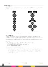
The LOX oxygen reduction system is delivered as a complete installation. On the next page a schematic overview of the
complete system and its components can be found. The drawing also shows that a distinction can be made between the LOX
unit and the area(
‘
s) to be protected.
The LOX system is usually installed separately from the room(s) to be protected, for example in the technical room. A
complete LOX system consists of:
•
Compressed air facility;
•
Water and oil separators;
•
Compressed air buffer tank;
•
One or more air dryers;
•
Liquid and residual dust filters;
•
Moisture detection sensor;
•
The nitrogen generator(s);
•
Dust filter(s);
•
Nitrogen flow and purity measurement;
•
Control cabinet;
•
Piping for nitrogen supply;
•
Flashing light;
•
Acoustic alarm (slowwhoop / evacuation alarm);
•
Door display at each access door;
•
Communication equipment for communication with the supplier's failure department;
•
Electrical cabling for the control centre(s), oxygen measuring equipment, alarm detectors and access control
equipment.
The LOX oxygen reduction system serves a maximum of 24 rooms. The following components are installed in each of these
rooms:
•
Supply points for nitrogen;
•
3 oxygen sensors (minimum 3 according to EN 16750);
•
Flashing light;
•
Acoustic alarm (slowwhoop / evacuation alarm);
•
Door display at each entrance door except for automatic sluices.
If the LOX oxygen reduction system is used to protect a refrigerated area where the temperature is below 0 °C, an alternative
assembly is used. In this application, the following components are placed outside the protected areas:
•
Flashing light;
•
Acoustic alarm (slowwhoop / evacuation alarm);
•
Door display at each entrance door except for automatic sluices.
Summary of Contents for LOX
Page 2: ...2 ...
Page 8: ...8 Figure 1 Schematic setup of the LOX system basics ...
Page 45: ......
Page 46: ......

