9.45, 9.45i Treadmill
Page 4
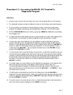
Procedure 2.1 - Accessing the M9.45 (1L or 2P) Treadmill's
Diagnostic Program
Procedure
1.
Plug the power cord into the wall outlet, then turn on the treadmill with the circuit breaker.
2.
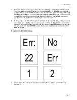
The diagnostic program provide six different routines to aid it testing and trouble diagnosis.
3.
On 9.45 (1Y & 2P units), with the
PRECOR M9.45
banner scrolling, press and hold
ENTER
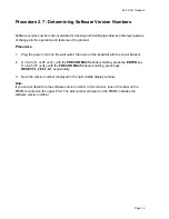
until the software version number is displayed in the right display windows. On units that
have serial numbers starting with '2P', the part number of the PROM will also be displayed.
4.
The first routine is the LED display test. The routine will light every LED on the display as the
test proceeds. It is necessary to watch the display to see if an LED does not light.
5.
On 9.45 (1L units) the second routine is the lift test. The lift test takes the lift through each of
the critical lift positions. In doing so it tests the performance of the zero switch, upper limit
switch, lower limit switch and rotation sensor. Press
ENTER
to continue.
6.
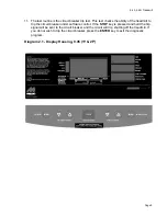
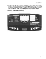
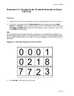
On 9.45 (2P) units the second routine is lift calibration. The lift calibration number indicates
the physical position of the lift. As lift is operated the lift calibration number will track the lift’s
physical position. The lift calibration number will be used to initialize the lift. Press the
INCLINE
keys while you watch the right display window (see Diagram 2.1). The lift
calibration number increments as the
INCLINE
▲
key is pressed and decrements as the
INCLINE
▼
key is pressed. Press
ENTER
to continue.
7.
The third routine is the power bits display. Power bits is a number that indicates the amount
of time that power is applied to the drive motor (duty cycle). The power bit number reflects
changes in speed and load. Power bits and running belt speed will; be displayed. Notice that
the power bits number will increase or decrease as speed and/or load is increased or
decreased. The power bit number can be used to determine treadmill loading. Press
ENTER
to continue.
8.
The fourth routine is the keypad test. Seven dashed lines will appear on the display. Each
dash will correspond to a key on the display. Press each key one at a time, the
corresponding dash will enlargen, indicating the key that was pressed. Use this test to
determine if the keys are functioning properly. Press the
INCLINE
▼
and
SPEED
▲
keys,
simultaneously to continue.
9.
The fourth routine is the safety key test. When the safety key is inserted
SAFE ON
is
displayed in the right display window. Remove the safety key from the upper display module
while you watch the right display window,
SAFE OFF
is displayed. Replace the safety key
and press
ENTER
to continue.
10. The fifth routine is the heart rate test. When a chest strap transmitter or test transmitter is
used, the heart rate will be displayed. Press
ENTER
to continue.
Summary of Contents for 9.45
Page 55: ...9 45 9 45i Treadmill Page 55 Wiring Diagram 7 1 9 45 1L Unit...
Page 56: ...9 45 9 45i Treadmill Page 56 Block Diagram 7 2 9 45 1L Units...
Page 57: ...9 45 9 45i Treadmill Page 57 Wiring Diagram 7 3 9 45 2P 3Y Units...
Page 58: ...9 45 9 45i Treadmill Page 58 Block Diagram 7 4 9 45 2P 3Y Units...


