9.45, 9.45i Treadmill
Page 28
10. Measure the voltage between the red wire (term. 4 of J3) and the black wire (term 1 of J3).
The voltage should read a constant 5 Vdc. If the voltage is 0 or significantly lower than 5
Vdc, disconnect the rotation sensor connector from the lower PCA. Measure the voltage
between the red wire (term. 4 of J3) and the black wire (term 1 of J3) on the lower PCA. If
the voltage is still 0 Vdc or significantly low, replace the lower PCA. If the voltage is now
correct, replace the hall effect sensor.
Note:
If possible set the lift in a position that does not operate the zero sense switch. The zero sense
switch may be operated by hand to perform the tests in step 11.
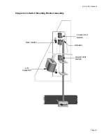
11. At this point the hall effect sensor is functioning normally, but lift errors occur. With a DC
voltmeter measure the voltage across the zero sense (center) switch. It should measure
approximately 0 Vdc when the switch is not operated and approximately 5 Vdc when the
switch is operated. If the operated voltage is 0 Vdc or significantly low, remove both blue
wires from the zero sense switch. Measure the voltage between the two blue wires. If the
voltage is now correct replace the zero sense switch. If the voltage is still O Vdc or
significantly low, replace the lower PCA.
12. At this point the hall effect sensor and the zero sense switch are functioning normally, but lift
errors occur. There are three potential causes for this condition. They are lower PCA, ribbon
cable or upper PCA. There are no good means of troubleshooting these components other
than substituting known good components. Replace only one component at a time. If the
component that you replaced does not correct the problem, replace the original component.
Try substituting the lower PCA first, the ribbon cable second and the upper PCA third. If you
have performed all of the above procedures and have been unable to correct the problem,
call Precor Customer Support.
Summary of Contents for 9.45
Page 55: ...9 45 9 45i Treadmill Page 55 Wiring Diagram 7 1 9 45 1L Unit...
Page 56: ...9 45 9 45i Treadmill Page 56 Block Diagram 7 2 9 45 1L Units...
Page 57: ...9 45 9 45i Treadmill Page 57 Wiring Diagram 7 3 9 45 2P 3Y Units...
Page 58: ...9 45 9 45i Treadmill Page 58 Block Diagram 7 4 9 45 2P 3Y Units...

