905E, 9.1, 9.10 Treadmills
Page 14
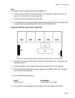
10. Loosen the screw that secures the crank handle to the electronic console. Remove the
crank handle and set it aside.
11. Remove the bolts and washers that secure the electronic console to the upper handrail
clamp.
12. Carefully move the electronic console, with the ribbon cable still attached, until it can rest on
the right handrail. The lift jack shaft and potentiometer are exposed.
13. Position the crank handle on the lift jack shaft and tighten the crank handle screw.
14. See Diagram 9.1-4. Watching the pin wheel, slowly rotate the crank handle until the drive
wheel is disengaged from the pinwheel.
15. If the PROM version number recorded in Step 9 is equal to or greater than 4.0
. . .
THEN . . .
OTHERWISE . . .
Rotate the pin wheel until the
Rotate the pin wheel until the
electronic console displays 18.
electronic console displays 10 - 12.
16. Place the magnetic safety key in the
OFF
position, then unplug the treadmill from the wall
outlet.
17. Loosen the crank handle screw and remove the crank handle from the electronic console.
18. Place the electronic console over the lift jack shaft and potentiometer.
19. Replace the two bolts and washers that secure the electronic console to the upper handrail
clamp.
20. Position the crank handle at its mounting position. Tighten the screw that secures the crank
handle to the electronic console.
Note:
On units that have set screws securing the crank handle, one of the set screws on the crank
handle must face the flat area on the lift jack shaft.
Summary of Contents for 9.10
Page 5: ...905E 9 1 9 10 Treadmills Page 5 9 1 Electronic Console 9 10 Electronic Console...
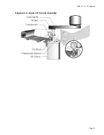
Page 15: ...905E 9 1 9 10 Treadmills Page 15 Diagram 4 2 Upper Lift Column Assembly...
Page 44: ...905E 9 1 9 10 Treadmills Page 44 Diagram 7 1 Wiring Diagram 905e 9 1 9 10...
Page 45: ...905E 9 1 9 10 Treadmills Page 45 Diagram 7 2 Block Diagram 905e 9 1 9 10 Treadmills...


