905E, 9.1, 9.10 Treadmills
Page 4
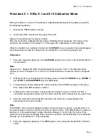
Procedure 2.1 - 905e, 9.1 and 9.10 Calibration Mode
Placing the 905e, 9.1 and 9.10 Treadmills in Calibration Mode causes the software to perform
the following operations:
1.
Display the PROM version number;
2.
Check the LED’s mounted on the upper PCA; and
Display the potentiometer increment number.
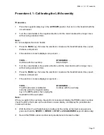
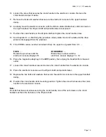
Place the treadmill in Calibration Mode before calibrating the lift assembly. (The steps in this
procedure are included in Procedure 4.1 of this appendix, Calibrating the Lift Assembly).
When the treadmill is in calibration mode and the
SPEED
▲
key is selected, the treadmill speed
will increase twice as fast as it does when the treadmill is in a normal operating mode.
Procedure
1.
Place the magnetic safety key in the
ACTIVATE
position, then turn on the treadmill with the
circuit breaker.
Note:
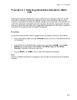
Diagram 9.1-1 displays the 905e Treadmill electronic console. The 9.1 Treadmill electronic
console is shown in Diagram 9.1-2. The 9.10 Treadmill electronic console is shown in Diagram
9.1-3.
2.
With the Enter Your Weight banner scrolling, press and hold the
SPEED
▲
key,
SPEED
▼
key,
STOP
, and
SCAN/ENTER
keys simultaneously.
3.
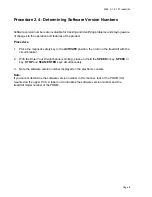
The electronic console displays the version number of the PROM mounted on the upper
PCA. Record the PROM version number.
4.
Following the version number, a horizontal line sweeps from top to bottom and then a
vertical line sweeps from right to left. The lines check the LED’s mounted on the upper PCA.
5.
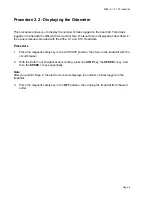
After the horizontal and vertical LED test lines, the electronic console displays the
potentiometer increment number.
Note:
If the PROM version number displayed earlier in this procedure is equal to or greater than 4.0,
the potentiometer increment number should be 18 @ 0% incline. if the PROM version number is
less than 4.0, the potentiometer number should be between 10 and 12 @ 0% incline. If the
electronic console does not display these increment numbers, the lift assembly is not calibrated
correctly. Go to Procedure 4.1 of this appendix.
6.
Place the magnetic safety key in the
OFF
position, then unplug the treadmill from the wall
outlet.
Summary of Contents for 9.10
Page 5: ...905E 9 1 9 10 Treadmills Page 5 9 1 Electronic Console 9 10 Electronic Console...
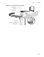
Page 15: ...905E 9 1 9 10 Treadmills Page 15 Diagram 4 2 Upper Lift Column Assembly...
Page 44: ...905E 9 1 9 10 Treadmills Page 44 Diagram 7 1 Wiring Diagram 905e 9 1 9 10...
Page 45: ...905E 9 1 9 10 Treadmills Page 45 Diagram 7 2 Block Diagram 905e 9 1 9 10 Treadmills...


