background image

Model PD650 Large Display Process Meter 

Instruction Manual


23 


Power Connections 

!


Refer to 

Changing from 115 to 230 VAC Power

, page 20, to make sure meter 

is set up to accept proper voltage before applying power. 

!


Disconnect power to the meter before making any connections. 

!


Do not connect Power or Earth Ground to any unused or CM terminals. 


Connecting 230 VAC with 115 VAC selected will result in damage to the 
instrument as well as endanger personnel. Connecting AC power when meter is 
set up for DC power will result in damage to the instrument as well as endanger 
personnel. 


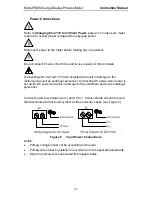
Connect power to terminals L2(V-) and L1(V+). Connect Earth Ground to screw 
terminal marked with Ground symbol on the enclosure’s base (see Figure 3). 


Figure 5. 

Input Power Connections 


Notice: 

• 

Primary voltages must not be accessible to the user. 

• 

Primary wires must be installed in accordance to the applicable standards. 

• 

Keep the primary wires separated from signal cables. 

Summary of Contents for PD650-2-34

Page 1: ...ull Six Digit Display for Total 4 Digit Extra Zero for Process Rate Total Displayed in any Engineering Unit Display in Engineering Units Rate per Second Minute Hour or Day Scale Without a Calibrator 1...

Page 2: ...Model PD650 Large Display Process Meter Instruction Manual 2 Visit our Website http www predig com...

Page 3: ...Instructions 22 Terminals Designation 22 Power Connections 23 Signal Connections 24 Enter Acknowledgement and Reset Total Connections 26 Optional Relays 4 20 mA Output Terminals 26 Isolated 4 20 mA Ou...

Page 4: ...Set and Reset Points for Process Rate Alarms 54 Preset Values for Total Set Points 54 Preset Offset Values for Total Set Points OFFSET 54 Programming Alarm and Preset Values SEtPtS 55 4 20 mA Isolated...

Page 5: ...delay 80 Priority Batch Programming or Quick Presets 80 Batch Control with Varying Batch Sizes 80 Pump Alternation Control 81 Pump Alternation Typical Application 81 Switching Inductive Loads 82 AC a...

Page 6: ...ays and Status LED Identification 29 Figure 15 Two Point Calibration Flowchart 31 Figure 16 JP1 Input Signal Selection Array 32 Figure 17 Display Showing Location of Set Point LEDs 55 Figure 18 Displa...

Page 7: ...ps Options include up to 4 relays for alarms or batch controlling as well as an isolated 4 20 mA transmitter output Features This model contains several features of interest Two 24 VDC Isolated Transm...

Page 8: ...hanger Display and Alarm Boiler Temperature Monitoring Gas Turbine Combustor Alarm Condenser Temperature Indicator Ordering Information 115 230 VAC Model 24 VDC Model Options Installed Option Cards PD...

Page 9: ...this meter in a fail safe system that accommodates the possibility of meter failure or power failure WARNING Hazardous voltages exist within enclosure Installation and service should be performed only...

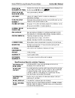
Page 10: ...n Error message will appear if input 1 signal and input 2 signal are too close together Input Range Minimum Difference Between Input 1 Input 2 0 5 V 0 16 V 0 10 V 0 32 V 4 20 mA 1 60 mA INPUT IMPEDANC...

Page 11: ...blocks accept 22 to 12 AWG wire MOUNTING Enclosure contains four holes for wall mounting Panel mounting kit available OVERALL DIMENSIONS 4 9 x 14 3 x 3 2 125 mm x 362 mm x 81 mm WEIGHT 7 0 lbs 3 2 kg...

Page 12: ...reset This delay can be programmed anywhere from 1 to 999 seconds PRIORITY BATCH PROGRAMMING This feature allows the user to quickly change preset values without going into the main menu by holding t...

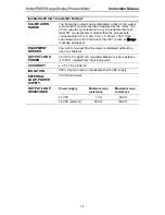
Page 13: ...o if set up for external total reset 2 After delay has elapsed if set up for internal total reset 3 Manual any time if set up for external total reset via user supplied external contact closure at ter...

Page 14: ...o 4 mA Ex 4 mA 0 20 mA 501 If the span between 4 and 20 mA is less than 501 counts an error message will appear EQUIPMENT NEEDED The 4 20 mA output from the meter is calibrated without the use of a ca...

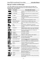
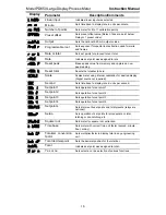
Page 15: ...nged under this function DspLAy Display Sets menu title scroll selections are activated with lockout jumper installed Dspy 1 Display 1 Sets display 1 calibration Dspy 2 Display 2 Sets display 2 calibr...

Page 16: ...o SCALE Scale Scales meter using internal calibration for desired display Signal source not required SeC Second Sets time base to display rate in units per second SEt 1 Set point 1 Sets operation for...

Page 17: ...ry default is 115 VAC b Labeling meter for input power 115 VAC 230 VAC or 24 VDC 3 Connections Page 21 a Power b Input signal c Enter acknowledgement and reset total d Relays e 4 20 mA output 4 Progra...

Page 18: ...ibed on page 20 Set configuration jumpers connect power and signal wires 6 Reassemble the Display Board prior to applying power 7 To program meter using front panel buttons leave top cover off until m...

Page 19: ...iagram Input signal and Lockout JP1 Main Board Figure 3 Relay ACK enable JP5 Display Board Figure 14 Fail safe J5 Options Board Figure 4 Input Selection and Lockout Jumpers Jumper JP1 Position Functio...

Page 20: ...ltage to DC powered meters Applying an AC voltage to DC powered meters will result in damage to the meter and endanger personnel Changing from 115 to 230 VAC Power To access the 115 230 VAC switch it...

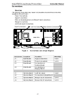
Page 21: ...Connections 4 20 mA Output Connections OPTIONS PCB MAIN PCB Figure 3 Connections and Jumper Diagram Connector Location Function Wire Size J1 Main Board Signal connections 12 22 J2 Main Board Power co...

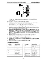
Page 22: ...0 volt 60 C If using AWG 20 or smaller wire up to two wires may be connected to each terminal If using AWG 18 or larger wire only one wire may be connected to each terminal 4 Install conduit hubs to t...

Page 23: ...C selected will result in damage to the instrument as well as endanger personnel Connecting AC power when meter is set up for DC power will result in damage to the instrument as well as endanger perso...

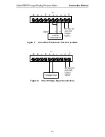
Page 24: ...tions are made to a 10 position connector J1 on the Main Board This connector also includes connections for Enter Acknowledgement Reset Total and Common Refer to Figure 3 for location of J1 Figure 6 T...

Page 25: ...Model PD650 Large Display Process Meter Instruction Manual 25 3 Wire Transducer Figure 8 Three Wire Transducer Powered by Meter Figure 9 Direct Voltage Signal Connections...

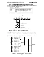
Page 26: ...ld reading switch ACK switch ENTER switch Figure 10 External Control Connections Optional Relays 4 20 mA Output Terminals Depending on the model number the Options Board may contain 2 or 4 relays and...

Page 27: ...he input loop and the isolated 4 20 mA output loop The following diagrams illustrate the 4 20 mA output signal being powered from the meter s internal power supply AC powered units only and by an exte...

Page 28: ...at have to be performed As each step progresses either a single digit or the entire display will flash The flashing digit or flashing display will be looking for acknowledgement if it is the desired d...

Page 29: ...panel on the Display Board It is labeled SW2 in Figure 14 above The ENTER button can also be accessed by wiring a normally open pushbutton switch across terminals EN and CM on connector J1 located on...

Page 30: ...ctions in the order shown Display Type of Function Dspy r or Dspy t Displays process rate or display total Rset t Resets total to zero Dspy p Displays and hold peak reading CALIb or SCale Calibrates m...

Page 31: ...Inpt1 flashes Apply input 1 signal e g 4 mA Inpt 2 flashes Apply input 2 signal e g 20 mA Press ENTER Is flashing display OK Wait for digit to flash Is flashing digit OK Press ENTER Is entire display...

Page 32: ...array JP1 located on the Main Board to the right of the transformer Figure 16 JP1 Input Signal Selection Array The meter can also be programmed to restrict personnel from making changes to the meter s...

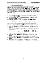
Page 33: ...eter with internal source press ENTER when I CAL appears Initial Calibration With External Source if Needed For best results allow the meter to warm up for at least 30 minutes Initial calibration is r...

Page 34: ...le root function is used for open channel flow measurement using weirs and flumes LInEAr then SquArE then Pro9 r Select linear input To select linear press ENTER when LInear is displayed The meter wil...

Page 35: ...for display 1 Dspy 1 as described above when the input for the first calibration point was programmed 00 000 final display 1 02 500 To quit main menu calibration or scaling press ACK while displaying...

Page 36: ...mmed 10 000 final display 2 05 000 Set the display for the remaining calibration points If other calibration points were selected they will be displayed and can be set according to the procedure for t...

Page 37: ...ted flow rate is equal to zero 04 000 Set the display for the first calibration point Display 1 Dspy 1 flashes indicating that the meter is ready to be programmed for the display for the first calibra...

Page 38: ...and flumes LInEAr then SquArE then Pro9 r Select linear input To select linear press ENTER when LInear is displayed The meter will now advance to setting the decimal point for process rate LInEar Set...

Page 39: ...o Minimum Input Span Error Message page 35 Apply signal for the second calibration point Input 2 INPT 2 flashes indicating that the meter is ready to accept a signal for the second calibration point A...

Page 40: ...Volume 1 4 00 0 00 2 4 80 1 90 3 6 40 9 50 4 8 40 22 40 5 15 60 77 70 6 17 60 90 50 7 19 20 98 10 8 20 00 100 00 Calibration Error error A meter display of Error during calibration indicates that the...

Page 41: ...ate and programming the low flow cutoff if required Set Display to Rate dSPy r The user may select either process rate or total to be set as the default displayed reading When displaying process rate...

Page 42: ...e meter accumulates based on the rate display This means that when the rate display is zero even as a result of the low flow cutoff the totalizer will not accumulate To set the low flow cutoff point P...

Page 43: ...int 5 Set Alternating Display if Needed Set Display for Total dSPy t The user may select either process rate or total to be set as the default displayed reading When displaying process rate the green...

Page 44: ...r is a number that is multiplied by the rate to compute the total For example if the rate display is gallons per hour and total is desired in barrels 1 gallon 0 02381 barrels a total conversion factor...

Page 45: ...splay will flash for three seconds For instructions see Five Basic Digit Display Setting Instructions page 30 0 01000 then 0 02000 then 0 02380 final 0 02381 Set Totalizer Decimal Point tot dp The tot...

Page 46: ...Y t Yes or no Y or n will flash alternately Press ENTER when n appears Y or n Note Selections made through the display menu dSPLAY can be made with or without the lockout jumper installed but only bec...

Page 47: ...cts are connected to the Common contacts of the relays The fail safe operation can be disabled by removing jumper J5 located on the Options Board 3 Setting set point functions using SETuP menu a Selec...

Page 48: ...JP5 Jumper Position SETuP Menu Automatic only after passing reset point Off Non latching Automatic manual at any time On Non latching Manual only at any time On Latching Manual only after passing res...

Page 49: ...ill automatically reset after the delay on release elapses allowing a new batch to begin If external total reset is selected relays must be reset manually Total relays also reset when total is reset t...

Page 50: ...If ENTER is pressed while set point 1 SEt 1 is shown the display will then show rate or total r or t flashing alternately Select the desired one by pressing ENTER when it is flashing SEt 1 then R or t...

Page 51: ...elect the desired one by pressing ENTER when it is flashing SEt 2 then r or t Select process rate After selecting r for process rate the display will show latch LatCH Press ENTER to program this funct...

Page 52: ...lashing After making the selection setup of set point 2 is complete and the next set point will be displayed Press ENTER to set up that set point if not wait until desired set point is displayed or wa...

Page 53: ...rY status LEDs 1 4 flash in pairs To program relay pair to alternate press ENTER when desired pair is flashing To program relays for independent operation not to alternate press ENTER when all status...

Page 54: ...value than the reset point Example To program an alarm for a high alarm at 500 with 100 counts of deadband program set and reset points as follows Set point 500 Reset point 400 Preset Values for Tota...

Page 55: ...offset value needs to be programmed The 4 discrete LEDs to the left of the display indicate which set point is being programmed Figure 17 Display Showing Location of Set Point LEDs For set points ass...

Page 56: ...1 SEt 1 will be displayed Press ENTER to program set point 1 or wait and the display will move to the next set point When set point 4 set 4 is shown the meter will exit the set points SetptS menu and...

Page 57: ...ED being illuminated The reset point is programmed in the same fashion as the set point above Meter displaying alarm 1 reset point Press ENTER then press ENTER again when the set points SetPtS functio...

Page 58: ...mber of counts before the second relay This is called the preset offset value and it is programmed as the first preset in a pair of set points setup for offset The second value in a pair of set points...

Page 59: ...ill flash for three seconds For instructions see Five Basic Digit Display Setting Instructions page 30 00000 final 00032 Set the display for value at which 20 mA is produced The green LED labeled 20 w...

Page 60: ...d When ENTER is pressed with the lockout jumper in place SCale CalIb Cutoff Tbase Tot Cf and Tot dP do not appear during the menu scroll and thus cannot be modified SetPtS menu title always appears Ab...

Page 61: ...he wants and disable the SEtPtS menu thus making it impossible for a user to change the batch presets by using the dSPLAy menu When the supervisor wants to change the batch presets he can reactivate...

Page 62: ...for SEtPtS will still allow an operator to view set reset points and presets but not to make changes 6 Select n for both dSPy r and dSPy t to program display to toggle between rate and total every 10...

Page 63: ...function in menu scroll press ENTER when y is displayed To exclude it press ENTER when n is displayed y or n Set menu scroll to include exclude reset total Reset total Rset t will appear for 3 seconds...

Page 64: ...DC power supplies to drive both the input and output loops Options include up to 4 relays for alarms or batch control applications as well as an isolated 4 20 mA transmitter output Figure 22 Front Pan...

Page 65: ...atus of the alarm condition For instance when a latching relay is acknowledged the corresponding status LED will extinguish Two Types of Display Process Rate and Total The meter also has the capabilit...

Page 66: ...ns are located behind the front panel and are accessible with the cover removed The functions of the ENTER and ACK buttons are brought out to screw terminals to provide remote access to these function...

Page 67: ...R LED on the right side Reset Peak Reading Press ENTER then press ENTER again when the reset peak Rset P menu title appears Rset P Meter returns to displaying current value The meter is now displaying...

Page 68: ...nge the display from reading total to rate Press ENTER to begin scrolling through the functions When display rate dspy r appears press ENTER The meter now displays rate and the green R LED on the righ...

Page 69: ...ernal switch closure or when the meter reaches the highest preset value Display Total dSPy t The user may toggle between a display of process rate or total at any time When displaying process rate the...

Page 70: ...Rate Time base Total conv factor Total after one second Total after one minute Total after one hour Total after one day 60 GPM Min 0 2 0 2 can 12 cans 720 cans 17280 cans In the above application 5 g...

Page 71: ...the menu scroll See Display Selection dSPLAy page 61 for details Resetting Total via External Contact Closure The total may be reset at any time by closing a normally open push button switch that is...

Page 72: ...and 3 Automatic Batch Control 4 Manual Batch Control Relays Auto Initialization When power is applied to the meter the front panel LEDs and alarm relays will reflect the state of the input to the mete...

Page 73: ...require visual only indication The front panel LEDs are controlled by the set and reset points programmed by the user When the display passes a set point for a particular alarm that alarm s LED will l...

Page 74: ...goes Off Non Latching Relay Automatic manual reset at any time JP5 1 4 on Condition LED Relay Normal Off Off Alarm On On Normal Off Off In this application the meter is set up for automatic manual res...

Page 75: ...Relay Normal Off Off Alarm On On Normal On On Ack Off Off In this application the meter is set up for manual reset only after the signal passes the reset point of the latching relay When the alarm is...

Page 76: ...ration The meter can be used as a simple On Off controller as the following illustrates Using the meter for sump pump control and alarm control Relay 1 turns the main pump on at 6000 gallons and turns...

Page 77: ...50 Large Display Process Meter Instruction Manual 77 Relay 3 trips the High Level Alarm at 7500 gallons and resets at 6900 gallons Relay 4 trips the Low Level Alarm at 495 gallons and it resets at 750...

Page 78: ...dribbles in the remaining 5 gallons When total reaches 55 00 relay 2 trips and closes restricted flow valve 2 Display freezes on 55 00 and relays 1 and 2 will not reset until external switch is pushe...

Page 79: ...The meter displays the barrel s content Full flow valve 1 is closed and restricted flow valve 2 dribbles in the remaining 5 gallons When the total reaches 55 00 gallons relay 2 trips and the restrict...

Page 80: ...o start a new batch Priority Batch Programming or Quick Presets For some batch control applications it may be necessary to change the presets frequently The meter has a quick preset change feature tha...

Page 81: ...d for low and high alarm indication respectively Set and reset point programming Set point 1 30 00 Reset point 1 10 00 Controls pump 1 Set point 2 35 00 Reset point 2 5 00 Controls pump 2 Set point 3...

Page 82: ...6 AC and DC Loads Protection Choose R and C as follows R 0 5 to 1 for each volt across the contacts C 0 5 to 1 F for each amp through closed contacts Notes 1 Use capacitors rated for 240 VAC 2 Snubber...

Page 83: ...of the programming values is accomplished by installing the lockout jumper JP1 Excluding menu titles from the menu scroll is performed with the display menu Note Selections made through the display m...

Page 84: ...mount the instrument to a wall The dimensions for the mounting holes are shown in the following figure 13 49 342 6 13 54 344 0 0 25 6 2 dia typ 3 2 82 Figure 29 Wall Mounting Dimensions Procedure 1 Dr...

Page 85: ...s where it is required to mount the meter into a panel the PDA6504 panel mounting kit is available See Ordering Information on page 8 DECORATIVE BEZEL METER COVER PANEL METER BASE BRACKET Figure 30 Pa...

Page 86: ...kness 0 06 0 25 1 5 mm x 6 4 mm Longer bracket screws may be used for panel thickness up to 0 5 12 7 mm 2 Mounting space required 7 x 17 5 x 4 178 mm x 445 mm x102 mm HxWxD Meter cover extends 0 8 20...

Page 87: ...at the factory To disable relays fail safe operation it is necessary to remove the Display Board to gain access to the Options Board Option cards may be ordered separately Refer to the following inst...

Page 88: ...cable connector 3 Remove the two right side standoffs and plastic washers discard the two plastic washers 4 Install Options Board using the two standoffs removed in step 3 5 Connect the flexible cabl...

Page 89: ...r Display Factory Setting User Setting Input range SEL 20 4 20 mA Calibration mode CALIb E Cal External calibration Type of signal LInEAr Linear input Process rate decimal point 299 99 Number of point...

Page 90: ...y Factory Setting User Setting Total reset mode e rst External total reset Set point values Set 1 1000 Set 2 4000 Set 3 70 00 Reset 3 60 00 Set 4 90 00 Reset 4 80 00 4 20 mA output 4 mA 000 00 20 mA 1...

Page 91: ...play 1 dspy 1 Input 2 InPt 2 Display 2 dspy 2 Input 3 InPt 3 Display 3 dspy 3 Input 4 InPt 4 Display 4 dspy 4 Input 5 InPt 5 Display 5 dspy 5 Input 6 InPt 6 Display 6 dspy 6 Input 7 InPt 7 Display 7 d...

Page 92: ...tting Set point 1 SET 1 latCH Set point 2 SET 2 latCH OFFSEt Set point 3 SET 3 latCH OFFSEt Set point 4 SET 4 latCH OFFSEt Total reset mode I or E Delay on release delay Set point 1 Set 1 Reset point...

Page 93: ...enu will be helpful to determine if a wrong setting is causing the operation of the meter to be undesirable Operation When the diagnostic menu is entered the function and programmed parameter settings...

Page 94: ...6 3 Digit Loop Powered NEMA 4X Meter FM CSA PD687 3 Digit Loop Powered Exp Proof Meter FM CSA PD690 1 8 DIN Analog Input Process Meter UL Listed PD691 1 8 DIN Strain Gauge mV Input Meter UL Listed PD6...

Page 95: ...Model PD650 Large Display Process Meter Instruction Manual 95 NOTES...

Page 96: ...port please call 800 610 5239 or 508 655 7300 fax 508 655 8990 e mail support predig com For Sales Support or to place an order please call 800 343 1001 or 508 655 7300 fax 508 655 8990 e mail sales p...

Reviews: