background image

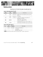
Installation

30

Powerware

®

5125 Installationsanleitung für IBM-Anwendungen

:

164201356 B

Uncontrolled Copy

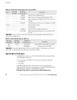
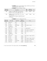
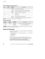
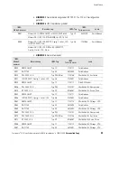
Tabelle 13. P33 Komponenten des Zubehörsatzes

Menge

IBM

Teilenummer

Powerware

Teilenummer

Bezeichnung

1

164201355

Powerware 5125 Benutzerhandbuch

1

164201356

Powerware 5125 Installationsanleitung für IBM-Anwendungen

3

60420055

Gerätestromkabel (6 Fuß/1,8 m) von IEC 320-C13 zu C14, 10 A

1

05146745-31

CD-ROM mit der Powerware Software-Reihe

1 Tüte

Kabelbinder

1

REPO-Anschluß

1

164201359

Benutzerhandbuch für Multi-Server Modul

3

124102022-002

Datenübertragungskabel USV-Server (DB-9 zu DB-9, 6 Fuß/1,8 m)

HINWEIS

Für Teile ohne IBM-Teilenummer wenden Sie sich an Powerware.

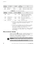
Tabelle 14. USV-Optionen

IBM

Modellnummer

IBM

Teilenummer

Powerware

Teilenummer

Bezeichnung

6607

21P7221

05147156-3901

Optionales erweitertes Batteriemodul (EBM) 2U*

2932

05146288-3901

Modul ConnectUPS-MX SNMP

*HINWEIS

An die USV können bis zu vier EBM angeschlossen werden. Wenn sich in einem Gestell zwei USVs befinden,

können an jeder USV bis zu zwei EBM angeschlossen werden.

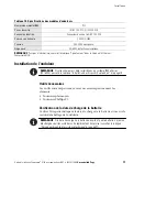
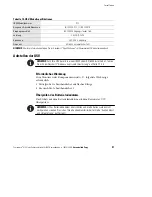
Elektrische Anforderungen

Für die USV ist ein eigener Stromzweig erforderlich, der die folgenden
Anforderungen erfüllt:

:

Steckdose für 200 - 240 V Wechselspannung, 16 - 32 A (Typ hängt
vom Land ab)

:

Einphasenstrom

:

50–60 Hz

Weitere Informationen entnehmen Sie bitte dem

pSeries Site and

Hardware Planning Information Guide

(Informationshandbuch für die

Site- und Hardware-Planung für pSeries / SA38-0508):

http://www-1.ibm.com/servers/eserver/pseries/library/hardware_docs

Summary of Contents for 5125 P33

Page 1: ...n Guide for IBM Applications Guide d installation pour applications IBM Installationsanleitung f r IBM Anwendungen Guida all installazione per le Applicazioni IBM Gu a de instalaci n para aplicaciones...

Page 2: ...xpress written approval of Powerware Corporation Copyright 2001 Powerware Corporation Raleigh NC Etats Unis Tous droits r serv s Aucune partie de ce document ne peut tre reproduite d une quelconque ma...

Page 3: ...Remote Emergency Power Off 8 Cord Connections 9 UPS Startup 15 Service and Support 15 TABLE DES MATI RES Installation 17 Sp cifications lectriques 18 Installation de l onduleur 19 Outils n cessaires 1...

Page 4: ...35 Erdungsschraube 35 Notausschaltung 36 Kabelanschl sse 38 Inbetriebnahme der USV 43 Kundendienst und Unterst tzung 43 SOMMARIO Installazione 45 Requisiti elettrici 46 Installazione dell UPS 47 Utens...

Page 5: ...Configuraci n del SIE 61 Herramientas necesarias 61 Verificaci n de la fecha de recarga de las bater as 61 Configuraci n de montaje en estante 62 Instalaci n de equipo opcional 63 Software de adminis...

Page 6: ...de for IBM Applications 164201356 B Uncontrolled Copy This page intentionally left blank Page intercalaire Diese Seite wurde absichtlich nicht bedruckt Questa pagina stata intenzionalmente lasciata bi...

Page 7: ...ccessory Kit 6630 21P7220 103002291 002 4 Post Rail Kit in shipping carton or factory installed in rack 9851 40H3018 1 NEMA L6 30R to IEC 320 C20P 6 ft 9851 40H3018 1 IEC 320 C19 to NEMA L6 30P 1 5 ft...

Page 8: ...6 ft 1 8m NOTE For those items without an IBM Part Number contact Powerware for additional parts Table 4 UPS Options IBM Model Number IBM Part Number Powerware Part Number Description 6607 21P7221 05...

Page 9: ...Specifications in the Powerware 5125 User s Guide UPS Setup NOTE If your UPS is already installed in an IBM pSeries RS 6000 system then skip to Installing Optional Equipment on page 5 Tools Required T...

Page 10: ...ive Use the following procedure to install the UPS in a rack 1 Place the UPS on a flat stable surface with the front of the UPS facing toward you 2 Attach the supplied mounting handles to the mounting...

Page 11: ...gement Software Ground Bonding Screw Remote Emergency Power Off switch Power Management Software If you are installing power management software use one of the supplied communication cables to connect...

Page 12: ...activated the UPS remains in Standby mode when restarted until the On button is pressed WARNING The REPO circuit is an IEC 60950 safety extra low voltage SELV circuit This circuit must be separated fr...

Page 13: ...the external REPO switch and restart the UPS Cord Connections Figure 4 shows a typical installation Figure 6 on page 10 shows four different rack configurations with cord connections NOTE Do not make...

Page 14: ...connected to each UPS Ground Bonding Screw UPS Battery Connector EBM Cable Output Receptacles Multi Server Module Port 1 EBM Battery Connectors Power Cord Circuit Breakers Figure 4 Typical Installatio...

Page 15: ...If you are using the Load Segment feature see the Powerware 5125 User s Guide for more information on controlling and assigning the load segments DO NOT protect laser printers with the UPS because of...

Page 16: ...1 NOTE 2A NOTE 2B NOTE 3 NOTE 4 NOTE 1 NOTE 1 NOTE 1 NOTE 2A NOTE 2B NOTE 2B NOTE 3 NOTE 3 NOTE 3 NOTE 3 P33 P33 P33 P33s Dual Redundant with PDB 9171 Dual Redundant with PDB 9174 and 9173 Dual Redun...

Page 17: ...4594 Various 9822 PDL 250V 30A Type PDL Wilco 11F0106 Required for Australia 9823 IEC 309 CEE17 2 pole 3 wire 32A Type 46 21H7693 Various 9824 NEMA L6 30P Type 12 11F0113 Many AFE countries 9826 PDL 2...

Page 18: ...BS 164 BS 546 Type 22 14F1557 Required for South Africa 9871 IEC 309 P N G 3 pin 16A Type 46 14F1555 Required for Denmark Switzerland and Liechtenstein 9872 SII 32 1971 Type 32 14F1561 Required for Is...

Page 19: ...o to www oem powerware com ibm ups then select your region The Americas North and South America EMEA Europe the Middle East and Africa APAC Asia Pacific and China Click Products 9910 Solutions and Pow...

Page 20: ...Installation 14 Powerware 5125 Installation Guide for IBM Applications 164201356 B Uncontrolled Copy This page intentionally left blank...

Page 21: ...du P33 6630 21P7220 103002291 002 Ensemble de rails pour 4 postes dans un carton d exp dition ou mont en usine dans une baie 9851 40H3018 1 NEMA L6 30R vers IEC 320 C20P 6 ft 9851 40H3018 1 IEC 320 C1...

Page 22: ...ant pas de num ro de pi ce IBM contactez Powerware pour obtenir des pi ces suppl mentaires Tableau 9 Articles optionnels pour onduleurs Num ro de mod le IBM Num ro de pi ce IBM Num ro de pi ce Powerwa...

Page 23: ...125 Installation de l onduleur REMARQUE Si votre onduleur est d j install dans un syst me IBM pSeries RS 6000 passez la rubrique Installation des dispositifs optionnels la page 19 Outils n cessaires L...

Page 24: ...u IBM contactez votre repr sentant Powerware Proc dez comme suit pour installer l onduleur dans une baie 1 Posez l onduleur sur une surface plane et stable en pla ant l avant de l onduleur face vous 2...

Page 25: ...nstall es avant de le mettre en marche Logiciel Power Management Vis de mise la terre Commutateur REPO de t l alimentation d urgence Logiciel Power Management Si vous installez le logiciel Power Manag...

Page 26: ...e mode Standby Attente quand on le red marre jusqu ce qu on appuie sur le Bouton On marche AVERTISSEMENT Le circuit REPO est un circuit SELV tension extra basse de s curit IEC 60950 Ce circuit doit tr...

Page 27: ...necteur REPO 5 Assurez vous que le commutateur REPO connect l ext rieur est en position OFF arr t afin de permettre l alimentation des prises de sortie de l onduleur 6 Branchez l onduleur et mettez le...

Page 28: ...c ble du module EBM dans le connecteur de batterie de l onduleur voir Figure 10 3 Branchez l autre extr mit du c ble du module EBM dans le connecteur de batterie du module EBM 4 Si vous installez un d...

Page 29: ...x prises de sortie appropri es de l onduleur REMARQUE Si vous utilisez les segments de chargement consultez le Guide de l utilisateur Powerware 5125 pour plus d informations sur le contr le et l attri...

Page 30: ...3 REMARQUE 4 REMARQUE 1 REMARQUE 1 REMARQUE 1 REMARQUE 2A REMARQUE 2B REMARQUE 2B REMARQUE 3 REMARQUE 3 REMARQUE 3 REMARQUE 3 P33 P33 P33 P33 Redondance avec PDB 9171 Redondance entre PDB 9174 et 9173...

Page 31: ...ption Type IBM Num ro de pi ce IBM Pays 9800 NEMA L6 30P Type 12 11F0113 Divers 9801 R S 3750 Type 40 46F4594 Divers 9822 PDL 250V 30A Type PDL Wilco 11F0106 N cessaire pour Australie 9823 IEC 309 CEE...

Page 32: ...nchez le cordon d alimentation amovible de l onduleur dans le connecteur d entr e situ sur le panneau arri re de l onduleur 9 Branchez le cordon d alimentation de l onduleur sur une prise secteur Tous...

Page 33: ...s et au Canada appelez le 1 800 IBMSERV 1 800 426 7378 En Europe au Moyen Orient et en Afrique en Am rique latine ou en Asie Pacifique appelez le centre IBM qui est en charge de votre compte Lorsque v...

Page 34: ...Installation 28 Guide d installation Powerware 5125 pour applications IBM 164201356 B Uncontrolled Copy Page intercalaire...

Page 35: ...beh rsatz 6630 21P7220 103002291 002 Schienensatz f r 4 St tzpfosten in Versandkarton oder werkseitig in Gestell installiert 9851 40H3018 1 NEMA L6 30R zu IEC 320 C20P 6 Fu 9851 40H3018 1 IEC 320 C19...

Page 36: ...Sie sich an Powerware Tabelle 14 USV Optionen IBM Modellnummer IBM Teilenummer Powerware Teilenummer Bezeichnung 6607 21P7221 05147156 3901 Optionales erweitertes Batteriemodul EBM 2U 2932 05146288 39...

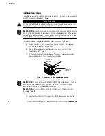
Page 37: ...handbuch Aufstellen der USV HINWEIS Falls Ihre USV bereits in einem IBM System RS 6000 installiert ist fahren Sie mit dem Abschnitt Einbau von optionaler Ausr stung auf Seite 33 fort Erforderliches We...

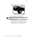
Page 38: ...n der USV in einem Gestell das nicht von IBM stammt wenden Sie sich an Ihren Powerware Vertreter Gehen Sie zum Installieren der USV in einem Gestell nach folgendem Verfahren vor 1 Die USV auf einer fl...

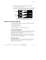
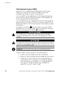
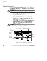
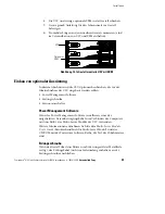
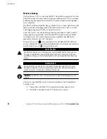
Page 39: ...der Inbetriebnahme der USV eingebaut werden sollten Power Management Software Erdungsschraube Fernnotausschalter Power Management Software Wenn Sie Power Management Software installieren eines der mit...

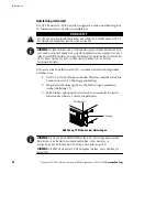
Page 40: ...rt der USV erfolgt ist Wenn die Taste Off Aus gedr ckt wird nachdem REPO aktiviert wird verbleibt die USV im Bereitschaftsmodus wenn diese neu gestartet wird bis die Taste On Ein gedr ckt wird ACHTUNG...

Page 41: ...15 Verseiltes nicht abgeschirmtes Kabel Gr e 18 22 AWG 0 75 mm2 0 mm2 verwenden 4 Den REPO Anschlu am REPO Anschlu an der R ckwand der USV anschlie en Stift 1 Stift 2 Abbildung 15 REPO Anschlu 5 berp...

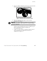
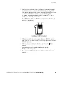
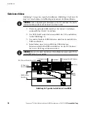
Page 42: ...ortfahren andernfalls bei Schritt 5 fortfahren 2 Das EBM Kabel an den Batterieanschlu der USV anschlie en siehe Abbildung 16 3 Das andere Ende des EBM Kabels an den Batterieanschlu des EBM anschlie en...

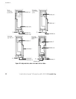
Page 43: ...enden Ger te an die entsprechenden Ausgangssteckdosen der USV anschlie en HINWEIS Wenn Sie die Ladesegment Funktion nutzen entnehmen Sie weitere Informationen ber die Steuerung und Zuweisung der Lades...

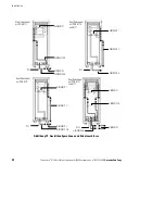
Page 44: ...S 2B HINWEIS 3 HINWEIS 4 HINWEIS 1 HINWEIS 1 HINWEIS 1 HINWEIS 2A HINWEIS 2B HINWEIS 2B HINWEIS 3 HINWEIS 3 HINWEIS 3 HINWEIS 3 P33 P33 P33 P33s Dual Redundant mit PDB 9171 Dual Redundant mit PDB 9174...

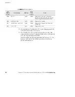
Page 45: ...p 40 46F4594 Verschiedene 9822 PDL 250 V 30 A Typ PDL Wilco 11F0106 Erforderlich f r Australien 9823 IEC 309 CEE17 2 polig 3 Leiter 32 A Typ 46 21H7693 Verschiedene 9824 NEMA L6 30P Typ 12 11F0113 Vie...

Page 46: ...2 14F1557 Erforderlich f r S dafrika 9871 IEC 309 P N G 3 polig 16 A Typ 46 14F1555 Erforderlich f r D nemark die Schweiz und Liechtenstein 9872 SII 32 1971 Typ 32 14F1561 Erforderlich f r Israel 8 Da...

Page 47: ...ie dort Ihre Region aus Amerika Nord und S damerika EMEA Europa Nahost und Afrika APAC Asien Pazifik und China Klicken Sie auf Products 9910 Solutions und Powerware pSeries Kundendienst und Unterst tz...

Page 48: ...Installation 42 Powerware 5125 Installationsanleitung f r IBM Anwendungen 164201356 B Uncontrolled Copy Diese Seite wurde absichtlich nicht bedruckt...

Page 49: ...220 103002291 002 Kit di guide per 4 alloggiamenti fornito con scatola d imballaggio o installato in fabbrica in rack 9851 40H3018 1 NEMA L6 30R IEC 320 C20P 1 8 m 6 ft 9851 40H3018 1 IEC 320 C19 NEMA...

Page 50: ...6 ft NOTA Per gli elementi che non possiedono un numero parte IBM contattare Powerware per le parti aggiuntive Tabella 19 Opzioni UPS IBM Numero modello IBM Numero parte Powerware Numero parte Descri...

Page 51: ...25 Manuale dell utente Installazione dell UPS NOTA Se l UPS gi installato in un sistema IBM pSeries RS 6000 passare alla sezione Installazione delle apparecchiature opzionali a pagina 47 Utensili rich...

Page 52: ...UPS in un rack seguire la procedura descritta di seguito 1 Collocare l UPS su una superficie piana e stabile con la parte anteriore dell UPS rivolta verso di voi 2 Collegare le maniglie di montaggio...

Page 53: ...Interruttore di spegnimento d emergenza remoto Software per la gestione del risparmio energetico Se si installa il software per la gestione del risparmio energetico utilizzare esclusivamente uno dei...

Page 54: ...alit Standby quando viene riavviato finch non viene premuto il Pulsante On AVVERTENZA Il circuito REPO un circuito di sicurezza a bassissima tensione SELV safety extra low voltage IEC 60950 Il circuit...

Page 55: ...riavviare l UPS Connessione dei cavi La Figura 22 mostra un installazione tipica La Figura 24 a pagina 52 mostra quattro configurazioni con connessioni dei cavi diverse per i rack NOTA L esecuzione di...

Page 56: ...iascun UPS Vite di collegamento a massa Connettore batteria UPS Cavo EBM Prese in uscita Porta 1 Modulo Multi Server Connettori batteria EBM Cavo alimentazione Interruttori Figura 22 Installazione tip...

Page 57: ...enti di carico consultare il Powerware 5125 Manuale dell utente per ulteriori informazioni sul controllo e l assegnazione dei segmenti di carico NON proteggere le stampanti laser con l UPS a causa del...

Page 58: ...A 1 NOTA 2A NOTA 2B NOTA 3 NOTA 4 NOTA 1 NOTA 1 NOTA 1 NOTA 2A NOTA 2B NOTA 2B NOTA 3 NOTA 3 NOTA 3 NOTA 3 P33 P33 P33 P33s Ridondante duale con PDB 9171 Ridondante duale con PDB 9174 e 9173 Ridondant...

Page 59: ...13 Varie 9801 R S 3750 Tipo 40 46F4594 Varie 9822 PDL 250V 30 A Tipo PDL Wilco 11F0106 Richiesto in Australia 9823 IEC 309 CEE17 bipolare a 3 fili 32 A Tipo 46 21H7693 Varie 9824 NEMA L6 30P Tipo 12 1...

Page 60: ...gresso del pannello posteriore dell UPS 9 Collegare il cavo di alimentazione dell UPS a una presa di corrente Tutti gli indicatori del pannello anteriore dell UPS lampeggiano brevemente mentre l UPS e...

Page 61: ...porto Per gli Stati Uniti e Canada chiamare il numero 1 800 IBMSERV 1 800 426 7378 In Europa Medio Oriente e Africa EMEA America Latina o Asia del Pacifico chiamare il numero Ufficio IBM per l assiste...

Page 62: ...Installazione 56 Powerware 5125 Guida all installazione per le Applicazioni IBM 164201356 B Uncontrolled Copy Questa pagina stata intenzionalmente lasciata bianca...

Page 63: ...6630 21P7220 103002291 002 Juego de riel de 4 postes en caja de cart n para env o o instalado de f brica en estante 9851 40H3018 1 NEMA L6 30R a IEC 320 C20P 6 pies 9851 40H3018 1 IEC 320 C19 a NEMA L...

Page 64: ...caso de los art culos que no tengan un N mero de parte de IBM comun quese con Powerware para obtener piezas adicionales Tabla 24 Opciones del SIE IBM N mero de modelo IBM N mero de parte Powerware N...

Page 65: ...ario de Powerware 5125 Configuraci n del SIE NOTA Si el SIE ya est instalado en un sistema IBM la Serie p RS 6000 podr pasar a Instalaci n de equipo opcional en la p gina 61 Herramientas necesarias Pa...

Page 66: ...ea de IBM comun quese con el representante de Powerware Utilice el siguiente procedimiento para instalar el SIE en el estante 1 Coloque el SIE en una superficie plana y estable con la parte frontal de...

Page 67: ...energ a Tornillo de uni n a tierra Interruptor de parada de emergencia remota Software de administraci n de energ a Si est instalando el software de administraci n de energ a utilice uno de los cables...

Page 68: ...do se reinicia hasta que se presione el Bot n On Encendido ADVERTENCIA El circuito de REPO es un circuito IEC 60950 de voltaje extra bajo de seguridad SELV por sus siglas en ingl s Este circuito debe...

Page 69: ...E Patilla 1 Patilla 2 Figura 27 Conector de REPO 5 Verifique que el interruptor de REPO conectado externamente est apagado para permitir que pase energ a a los recept culos de salida del SIE 6 Conecte...

Page 70: ...ntrario dir jase al paso 5 2 Conecte el cable del EBM al conector de bater a del SIE consulte la Figura 28 3 Conecte el otro extremo del cable del EBM en el conector de bater a del EBM 4 Si est instal...

Page 71: ...en los recept culos de salida del SIE adecuados NOTA Si est utilizando la caracter stica de Cargar segmento consulte la Gu a del usuario de Powerware 5125 para obtener m s informaci n sobre c mo cont...

Page 72: ...1 NOTA 2A NOTA 2B NOTA 3 NOTA 4 NOTA 1 NOTA 1 NOTA 1 NOTA 2A NOTA 2B NOTA 2B NOTA 3 NOTA 3 NOTA 3 NOTA 3 P33 P33 P33 P33 Redundante doble con PDB 9171 Redundante doble con PDB 9174 y 9173 Redundante...

Page 73: ...IBM Descripci n Tipo IBM N mero de parte de IBM Pa s 9800 NEMA L6 30P Tipo 12 11F0113 Varios 9801 R S 3750 Tipo 40 46F4594 Varios 9822 PDL 250V 30A Tipo PDL Wilco 11F0106 Requerido para Australia 982...

Page 74: ...tria Rep blica Checa Estonia Finlandia Rusia Letonia Lituania Portugal Suecia y Turqu a 9867 SABS 164 BS 546 Tipo 22 14F1557 Requerido para frica del Sur 9871 IEC 309 P N G 3 patillas 16A Tipo 46 14F1...

Page 75: ...www oem powerware com ibm ups y luego seleccione su regi n Las Am ricas Am rica del Norte y del Sur EMEA Europa el Medio Oriente y frica APAC Asia Pac fico y China Haga clic en Productos Soluciones 9...

Page 76: ...Instalaci n 70 Gu a de instalaci n de Powerware 5125 para aplicaciones de IBM 164201356 B Uncontrolled Copy Esta p gina se dejo en blanco intencionalmente...

Page 77: ...This page intentionally left blank...

Page 78: ...72 Powerware 5125 Installation Guide for IBM Applications 164201356 B Uncontrolled Copy 164201356 B 72...

Reviews: