background image

PFC SINEWAVE UPS SERIES

CP850PFCLCD/CP1000PFCLCDTAA

USER MANUAL

YOUR ULTIMATE ALLY IN POWER

Cyber Power Systems (USA), Inc.

4241 12th Avenue East, Suite 400  |  Shakopee, MN 55379  |  

CyberPowerSystems.com

FEATURES

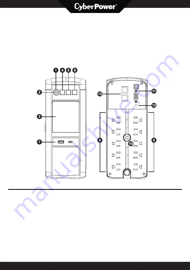
1.   Power Switch
2.   Power On Indicator
3.   LCD Module Display
4.   Down/Display Button
5.   Up/Mute Button
6.   Enter/Setup Button
7.   USB charging ports  

(Except for CP850PFCLCD)

8.   Battery and Surge Protected Outlets
9.   Full-time Surge Protected Outlets 
10.  Circuit Breaker
11.   DB9/USB Ports to PC
12.  Wiring Fault Indicator (red)
13.  Communication Protection Ports  

(RJ45)

Summary of Contents for AVR CP850PFCLCD

Page 1: ...erPowerSystems com FEATURES 1 Power Switch 2 Power On Indicator 3 LCD Module Display 4 Down Display Button 5 Up Mute Button 6 Enter Setup Button 7 USB charging ports Except for CP850PFCLCD 8 Battery a...

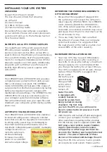
Page 2: ...ng a computer component CAUTION To reduce the risk of fire connect only to a circuit provided with 20 amperes maximum branch circuit over current protec tion in accordance with the National Electric C...

Page 3: ...re cor rected to safe levels AVR automatically increases low utility power to a consistent and safe output voltage DETERMINE THE POWER REQUIREMENTS OF YOUR EQUIPMENT 1 Ensure that the equipment plugge...

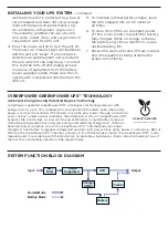
Page 4: ...the equipment being attached for proper accessibility SYSTEM FUNCTION BLOCK DIAGRAM EMI Filter Surge Suppressor AVR Charger AC DC Battery Inverter Input Output Normal Mode Battery Mode Advanced Energy...

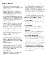
Page 5: ...p Guide 7 USB charging ports Except for CP850PFCLCD The USB Power ports Type A and Type C provide DC 5V 3 1A power output 8 Battery and Surge Protected Outlets The unit has 5 battery powered and surge...

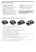
Page 6: ...ACING THE BATTERY BATTERY REPLACEMENT PROCEDURE CP850PFCLCD CP1000PFCLCD 1 Turn off and unplug all connected equipment 2 Turn the UPS off and unplug it from the AC power source 3 Turn the UPS on its s...

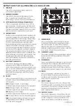
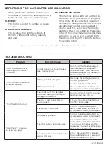
Page 7: ...T This icon appears if there is a problem with the UPS Press the POWER button to turn off the UPS E01 Charger Fault Overcharge Contact CyberPower Systems for support E02 Charger Fault No Charge Contac...

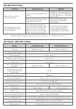
Page 8: ...teries at cyberpowersystems com support Mechanical problem Contact CyberPower Systems at cyberpowersystems com support PowerPanel is inactive all icons are gray The USB cable is not connected Connect...

Page 9: ...e cycles Recommended Battery Sealed Maintenance Free Lead Acid Battery Safety Approvals UL1778 CSA C22 2 No 107 3 FCC DoC Class B TROUBLESHOOTING Problem Possible Cause Solution PowerPanel is inactive...

Page 10: ...d and found to comply with the limits for a Class B digital device pursuant to part 15 of the FCC Rules These limits are designed to provide reasonable protection against harmful interference in a res...

Reviews: