background image

Cyberhawk-200M Installation

-

6 of 22 -

Doc. No: 202-003318-610 Rev A01

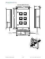
UNIT DIMENSIONS

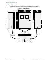
Unit dimensions and mounting details are illustrated following outline diagram.

Cyberhawk-200M-1/2P Outline

1

6

.6

"

1

7

.3

"

8

"

8

"

4

"

H

P

E

V/A

Multifunction Power Meter

H

P

E

V/A

Multifunction Power Meter

Summary of Contents for Cyberhawk-200M

Page 1: ...is Manual Risk of Electric Shock and or ARC Flash Hazard Life threatening voltages may be present with the risk of ARC Flash in the event of an inadvertent short circuit Cautionary Safety Alert Draws...

Page 2: ...cal and National Electric Codes such as National Electric Code NEC in the USA or Canadian Electric Code in Canada which governs the requirements for electrical wiring and protection These requirements...

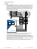
Page 3: ...ion 15 Amps max SOURCE LOAD CT Interface optional CT1 CT1 CT2 CT2 CT3 CT3 G L1 L2 L3 G N L1 L2 L3 N G CT1 CT1 CT2 CT2 CT3 CT3 5 Amp CTs H P E V A Multifunction Power Meter H P E V A Multifunction Powe...

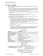
Page 4: ...ith min 1 32 in insulation rated minimum 600V and minimum of 105 C Note CT sizing is based on Bus current and the physical dimensions of the bus refer to table following CT Interface Terminal Blocks O...

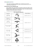
Page 5: ...r each meter port Note that wiring for the different system configurations are illustrated in this bulletin This will define the system voltage connections and the number of CTs required The following...

Page 6: ...c No 202 003318 610 Rev A01 UNIT DIMENSIONS Unit dimensions and mounting details are illustrated following outline diagram Cyberhawk 200M 1 2P Outline 16 6 17 3 8 8 4 H P E V A Multifunction Power Met...

Page 7: ...circuits 7 6 16 6 Wiring access Primary Voltages Class 1 circuits Network Cable Access 6 5 6 6 6 3 Meter 1 Meter 6 Meter 5 Meter 4 Meter 3 Meter 2 H P E V A Multifunction Power Meter H P E V A Multif...

Page 8: ...ents Loose connectors or connections Broken wires Mounting the Cyberhawk 200M xP Attach the mounting brackets to the Cyberhawk 200M xP with supplied mounting bracket hardware One of two types may be s...

Page 9: ...if fitted Note No splices on the CT secondary wires are permitted within the enclosure where installed or in the conduit through which the secondary wires are run Splices are only permitted as follow...

Page 10: ...Input L2 L1 L3 N GND LAN1 Ethernet F2 1 F2 2 F2 3 F1 1 F1 2 F1 3 CT3 CT2 CT1 CT3 CT1 CT2 Port 1 CTs Dig 3 Dig 2 Dig 1 Port 1 Digital I P Com GND R T B R T A COM GND RS485 CT3 CT2 CT1 CT3 CT1 CT2 Port...

Page 11: ...CT1 CT2 CT3 CT1 CT3 CT2 GND CT1 CT2 CT3 CT1 CT3 CT2 GND CT1 CT2 CT3 CT1 CT3 CT2 GND CT1 CT2 CT3 CT1 CT3 CT2 GND R T A R T B GND COM Meter 1 CT1 CT2 CT3 CT1 CT3 CT2 GND Meter 2 CT1 CT2 CT3 CT1 CT3 CT2...

Page 12: ...onnection must match e g CT1 on L1 etc Note For measurement of multiple circuits on a common Bus it is acceptable to wire all the voltage inputs to one disconnect device for voltage sensing to save on...

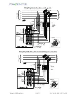
Page 13: ...Cyberhawk 200M Installation 13 of 22 Doc No 202 003318 610 Rev A01 Wiring Diagram for Single Phase 2 wire systems Wiring Diagram for Split Phase 3 wire systems CT1 CT1 CT2 CT2...

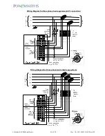
Page 14: ...Cyberhawk 200M Installation 14 of 22 Doc No 202 003318 610 Rev A01 Wiring Diagram for three phase 4 wire systems Wiring Diagram for three phase 3 wire systems 3 CT connection...

Page 15: ...Cyberhawk 200M Installation 15 of 22 Doc No 202 003318 610 Rev A01 Wiring Diagram for three phase 3 wire systems 2 CT connection Wiring Diagram for three phase 4 wire High Leg systems...

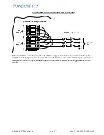
Page 16: ...nnection F2 1 Note Paralleling the Voltage Inputs to facilitate a single connection to the common Voltage Bus simplifies hookup by requiring only one Disconnect however all meters will display the sam...

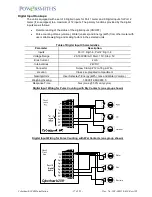
Page 17: ...in the selected units Table of Digital Input Characteristics Parameter Description Inputs Port 1 Dig 1 6 Port 2 Dig 1 6 Voltage Range 20 160VDC AC Start 15V Stop 5V Bias Current 2 mA Internal Bias 24V...

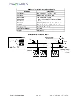
Page 18: ...cription Relay Connections Port 1 RO 1 RO 2 RO C Port 2 RO 1 RO 2 RO C Voltage Rating 250VAC 30VDC Current Rating 3A Resistive 2A Inductive Connector Screw Clamp 12 to 18 ga Wire Location Class 2 segr...

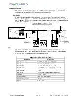
Page 19: ...wing for RS485 characteristics Typical RS485 Network Connection Notes The standard RS485 Port is directly supported by the Meters which will each have unique Modbus addresses 1 247 plus additional set...

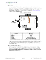
Page 20: ...500V Protocols TCP IP HTTP Modbus TCP IP Addressing DHCP Client dynamic and static Note Unit shipped with dynamic addressing enabled which may be changed to static at setup Note It may be advisable to...

Page 21: ...B Connector Screw Clamp 12 to 24 ga wire Baud Rates 9 6k 19 2k 38 4k 115 2k Data Format 1 Start 8 Bit no even odd parity 1 Stop Bit Max Range 1 200 m Max Load Standard 32 max transceivers on same bus...

Page 22: ...Power On Screens on Setup the Cyberhawk 200M xP for each meter following instructions given in the Operational Manual Setup may be done locally at the screen or by PC using the propriety setup softwa...

Reviews: