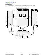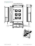
Cyberhawk-200M Installation
-
9 of 22 -
Doc. No: 202-003318-610 Rev A01
Current Transformers Installation
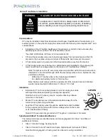
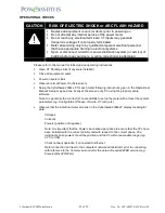
WARNING
HAZARD OF ELECTRIC SHOCK OR ARC FLASH
Risk of
Electric
Shock
To reduce risk of electric shock, always open or disconnect
circuit from power-distribution system (or service) of building
before installing or servicing current-sensing transformers
Considerations:
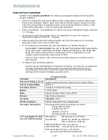
CTs may be installed in Electrical Enclosures, Switchgear, Switchboards, Panel-boards or in
auxiliary gutters on the current carrying bus wires under the following code requirements** and
considerations:
Installation of the CTs within Switchgear, Panel-boards or Gutters shall not reduce the
available space to more than 75% of its available volume*
*See NEC 2005 Article 312 Para: 312.8 and Article 366
CTs and the secondary wires are to be arranged away from live terminals and the CTs
secured to the bus wires using a minimum of three cable ties to prevent movement
CT secondary wires to be secured in their desired position away from the live bus
CT Secondary wires are to be feed in a dedicated conduit installed for the purpose (not
common with live bus voltage wires) to the meter or CT Interface Box (if fitted).
Note: No splices on the CT secondary wires are permitted within the enclosure where
installed or in the conduit through which the secondary wires are run. Splices are only
permitted as follows:
-
Within the CT Interface Box or the
Cyberhawk-300/MPC
-
In a dedicated Auxiliary Gutter or Terminal box
Note: Splices must comply with the requirements of the relevant local and national
electric codes S
ee NEC 2005 Article 110 Para: 110.14 (B)
Installation:
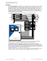
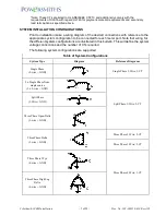
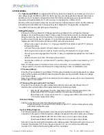
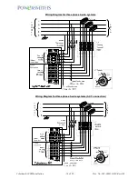
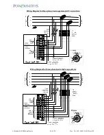
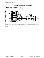
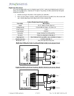
Install each CT on the required phases of current carrying bus wires
with regard to phase and polarity (see diagram opposite)
Note that errors in CT phasing may be corrected later by software
correction in the meter
Secure CT secondary wires in their desired position away from the
current carrying bus using cable ties
Feed the CT Secondary wires through the dedicated conduit installed
for the purpose (not common with live bus voltage wires) to the meter
or CT Interface Box (if fitted)
Note: All CTs are internally grounded at CT negative (-) terminals in the meter
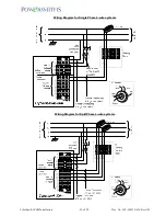
Cyberhawk-200M-xP Terminal Identification
The internal terminals are identified below and are segregated into Class 1 and Class 2
partitions as follows:
Class 1 Circuits: Voltage Sensing Inputs
Class 2 Circuits: Current Transformer Inputs, Digital Inputs (or Outputs if fitted)
Note that this segregation of wiring must be adhered to during installation


