background image


1.


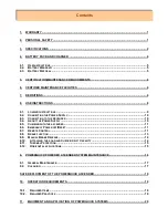
WARRANTY .......................................................................................................................................... 1


2.


PERSONAL SAFETY ........................................................................................................................... 1


3.


SPECIFICATIONS ................................................................................................................................ 2


4.


BATTERY PACK AND CHARGER ...................................................................................................... 4


4.1.


U

SE 

I

NSTRUCTIONS

 .............................................................................................................................. 5


4.2.


B

ATTERY 

W

ARRANTY

 ........................................................................................................................... 5


4.3.


B

ATTERY 

D

ISPOSAL

 ............................................................................................................................. 5


5.


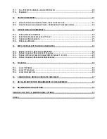
CERTIFICATION/MAINTENANCE REQUIREMENTS ......................................................................... 6


6.


CERTIFIED MAINTENANCE FACILITIES ........................................................................................... 6


7.


DEFINITIONS ........................................................................................................................................ 6


8.


USE INSTRUCTIONS ........................................................................................................................... 8


8.1.


L

OADING 

I

NSTRUCTIONS

 ....................................................................................................................... 9


8.2.


C

ONNECTING THE 

P

OWER 

S

UPPLY

 ...................................................................................................... 10


8.3.


C

ONNECTING TO THE 

A

SCENDER

 ........................................................................................................ 10


8.4.


A

BOUT THE 

P

OWER 

S

UPPLY

 ............................................................................................................... 10


8.5.


C

LIMBING WITH THE ASCENDER

 ........................................................................................................... 11


8.6.


E

MERGENCY 

P

OWER OFF

/R

ESET

 ........................................................................................................ 11


8.7.


R

EMOTE 

C

ONTROL

 ............................................................................................................................. 11


8.8.


B

RAKE FUNCTION

 ............................................................................................................................... 13


8.9.


M

ANUAL 

B

RAKE 

R

ELEASE

 .................................................................................................................. 14


8.10.


A

TTACHING THE 

L

OAD AND 

C

HECKING 

L

IFT 

C

APACITY

 ...................................................................... 14


8.11.


T

HERMAL 

P

ROTECTION

 .................................................................................................................... 15


8.12.


H

ORIZONTAL APPLICATIONS

 ............................................................................................................. 15


9.


POWERQUICK POWERED ASCENDER SYSTEM MAINTENANCE ............................................... 16


9.1.


G

ENERAL 

M

AINTENANCE

 .................................................................................................................... 17


9.2.


C

LEANING

 .......................................................................................................................................... 17


SAFE DEPLOYMENT OF THE POWERQUICK ASCENDER ................................................................... 19


10.


OPERATION REQUIREMENTS ....................................................................................................... 19


10.1.


R

EQUIRED 

I

TEMS

.............................................................................................................................. 19


10.2.


R

EQUIRED 

P

RACTICES

 ..................................................................................................................... 19


11.


EQUIPMENT AND APPLICATION OF POWERQUICK SYSTEMS ................................................ 20


Contents 

Summary of Contents for PQ 500-1

Page 1: ...4 ABOUT THE POWER SUPPLY 10 8 5 CLIMBING WITH THE ASCENDER 11 8 6 EMERGENCY POWER OFF RESET 11 8 7 REMOTE CONTROL 11 8 8 BRAKE FUNCTION 13 8 9 MANUAL BRAKE RELEASE 14 8 10 ATTACHING THE LOAD AND CHEC...

Page 2: ...S 23 13 4 ROPES AND RIGGING 23 14 EMPLOYEE SELECTION AND CAPABILITIES 24 14 1 DUTIES OF LEVEL 1 ROPE ACCESS WORKERS 25 14 2 DUTIES OF LEVEL 2 ROPE ACCESS TECHNICIAN 25 14 3 DUTIES OF ROPE ACCESS ATTEN...

Page 3: ...BS 7985 2002 British Standard Code of Practice The use of rope access methods for industrial purposes Guidelines on the use of rope access for industrial purposes Industrial Rope Access Trade Associa...

Page 4: ...0 1 1 W Wi it th h W Wi ir re el le es ss s R Re em mo ot te e C Co on nt tr ro ol l P PQ Q 5 50 00 0 T TR R W Wi it th h W Wi ir re el le es ss s a an nd d W Wi ir re ed d R Re em mo ot te e C Co on...

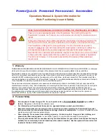
Page 5: ...use whichever comes first The Ascender must then undergo inspection and certification by a PowerQuick Concepts Inc qualified maintenance facility as discussed in Section 5 Once recertified the warrant...

Page 6: ...ures Compatible with standard climbing gear Must be used in accordance with manufacturers instructions meet applicable requirements and regulations Use with 1 2 in 12 7mm static low stretch kernmantle...

Page 7: ...pe prior to each use and periodically during use Power Supply NiMH Rechargeable Battery 36vdc 30 amp 360 amp minutes discharge to 25 vdc Climbing Time 500 to 600 feet 152 182m per charge Battery Pack...

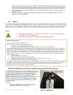
Page 8: ...ir ability to accept a charge at any time without suffering from the memory effect The best way to charge NiMH batteries is with regular charging Do not allow NiMH batteries to discharge below 25 VDC...

Page 9: ...year at room temperature 68 F are modified subjected to abuse physically damaged when allowed to discharge below 25 VDC or charged with a charging device not approved by PowerQuick Concepts Inc If the...

Page 10: ...ga Drive Carson City NV 89706 775 882 8100 http wwwpowerquickinc com email CustomerService powerquickinc com United Kingdom Point of Contact PowerQuick UK Park House 158 160 Arthur Road London SW19 8A...

Page 11: ...rofession of engineering Prime mover means the source of mechanical power for a machine Rated load means the manufacturer s recommended maximum load Rated strength means the strength of wire rope as d...

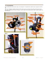
Page 12: ...operate The photos below show the major components of the PQ 500 Note This configuration is slightly changed in that the tension arm uses an improved rope locking mechanism and lower rope guide The lo...

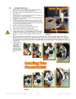
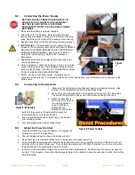
Page 13: ...outside capstan V grove 8 Guide the rope through the down rope guide 9 9 Tug on the rope to make sure it is seated in the capstan 10 Close and latch the cover THE ASCENDER WILL NOT OPERATE UNLESS THE...

Page 14: ...ke sure the climbing rope and fall arrest system is properly anchored See Section 12 We recommend the MIO Trailing Rope Grab 2 When Using the rope grab place a small weight at the bottom of the belay...

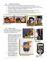
Page 15: ...cender is equipped with a wireless remote control The Transmitter and receive is certified for FCC Part 15 and Industry Canada RSP 100 compliance The 433 92MHz version has also been tested for CE comp...

Page 16: ...ngs where excessive microwave or other electrical signals interfere with the operation of the wireless remote Operations 1 Prepare the PowerQuick 500 for pendant operation by setting the UP DN lever t...

Page 17: ...the ascender turned OFF plug in the bite switch to the back of the pendant see Figure 17 d Ensure the selector switch is in the proper position as this will determine the direction of travel e Press t...

Page 18: ...subject to a 6 meter drop 1 The load is always attached to the load limiter loop Note Do not attach the load to any other part of the ascender 2 For proper function of the ascender DO NOT USE AT MORE...

Page 19: ...linking red light by the power switch Normal operation will return when the unit cools about 5 minutes This will be signified by a solid green light 8 13 Horizontal applications The PowerQuick can be...

Page 20: ...teries can attached at one time and attached to the spreader bar This configuration can only be used with Tower wired remote remote version A lanyard is attached to the manual release lever and thread...

Page 21: ...may be used to remove dirt and grease however do not immerse the PowerQuick unit in liquid 3 The capstan and all other parts shall be kept clean if their proper functioning would be affected by the p...

Page 22: ...he range of 1 16 to 1 8 inch This dual adjustment is necessary to keep the brake lever parallel to the top of the manual brake release housing d Testing for operation i Apply a 100 pound down load on...

Page 23: ...place by ascending or descending twin ropes fixed to secured anchorages The PowerQuick Powered Ascender is used in conjunction with approved climbing equipment to provide for safe controlled ascent an...

Page 24: ...levels of risk Whether it would be possible to quickly rescue workers that are using rope access techniques from any position they could be expected to enter 10 The employer shall designate a Rope Ac...

Page 25: ...ucturally adequate In either case the person making the assessment shall document this An example of where an engineer may not be required is where an anchorage sling of the correct capacity is secure...

Page 26: ...y on tall buildings A rule of thumb for consideration of restraints is 165 ft however they may be required well before this height on some buildings Windy conditions The PowerQuick Powered Ascender sh...

Page 27: ...lypropylene and Kevlar are types of ropes which may be considered in exceptional circumstances such as where there is severe chemical pollution or where the self weight of the ropes could be a problem...

Page 28: ...riate grounding shall be provided for as necessary Any power tools that could cause injury to the users or access equipment should be fitted with an automatic shut off switch that will cut off the pow...

Page 29: ...s Worker or Workers were appropriate 15 3 Duties of Rope Access Attendant May be Level 1 2 or 3 1 Monitor the Rope Access Technician Worker 2 Communicate with the Rope Access Technician Worker 3 Monit...

Page 30: ...nt and Safe Work Method statement Demonstrate a thorough knowledge of worksite organization Demonstrate a thorough knowledge of equipment usage and maintenance Complete the following safely maintainin...

Page 31: ...strength Do any weather conditions eg wind create a need for lateral restraint or other precautions Has fall protection prevention been arranged in the case of anchors being less than 2mtrs from a da...

Page 32: ...nd the Connector Check the textile part has not been replaced Check that the connectors meet ANSI or other safety requirements 18 1 8 Check of the Energy Absorption Function For sliding energy absorbe...

Page 33: ...iction components with a rag 18 3 6 Effectiveness of the Spring of the Security Catch Clean with a brush and soapy water if necessary oil with silicone Oil the pins and the spring Warning wipe the fri...

Page 34: ...Nylon Ring should be properly located on your back Adjustments are easier if you get help when first setting up the equipment 4 Adjust both right and left side shoulder straps so they are in the posi...

Page 35: ...eads which are cut stretched or worn When stitching is stretched check there is not cut thread 18 5 6 Condition of the Attachment Buckles Check on the attachment buckles at the front sides chest and r...

Page 36: ...wheel to tighten the headband as far as possible and then pull the headband to check that it does not loosen If the adjustment does not work the product must be rejected Warning do not pull the headba...

Page 37: ...eys 18 8 1 Condition of the Safety Elements Body Moving Side Pieces Sheave Grooves Rivet Axles It is important to thoroughly check the sidepieces for any cracks or marks seek out their cause sharp too...

Page 38: ...10 14 Requirements for Safety Belts Harnesses Lanyards Lifelines and Drop Lines for Construction and Industrial Use ANSI A39 1 Safety Requirements for Window Cleaning ANSI Z359 1 Safety Requirements f...

Page 39: ...ection systems criteria and practices OSHA 1915 160 Positioning device systems ANSI Z133 Safety in Tree Trimming Operations ANSI Z359 3 Assisted Rescue and Self Rescue Systems Industrial Rope Access T...

Page 40: ...supplied by the manufacturer and does not include any liability for special indirect or consequential damages The Purchaser s sole remedy for performance or non performance under these plans is limite...

Page 41: ...developed a flexible multi phase maintenance program that is tailored to individual user needs Rates and service schedules are provided in the table following the description of the options 5 1 Compre...

Page 42: ...ct Upgrades In the event that the technician determines that the PowerQuick ascender is not reparable or is not cost effective to repair as a result of normal wear and tear or user induced damage owne...

Page 43: ...he standard maintenance option package your ascender and ship it with a Request for Service to your authorized service center A maintenance request form is located at the end of this contract It is al...

Page 44: ...cation Buyer shall comply and require its employees to comply with all instructions given by PowerQuick Concepts Inc regarding installation use and maintenance of the equipment described herein and sh...

Page 45: ...following maintenance Option Standard Preventive Maintenance and Certification Comprehensive 24 Hour On Site Service We Decline a Maintenance Contract at this Time The undersigned hereby agree to the...

Page 46: ......

Page 47: ...aft Name On Card Expiration Date ____ ____ 20___ Purchase Order with approved Credit or CC Shipping Information if different from billing Address Company Name Contact Address Phone Number E Mail Billi...

Page 48: ...NOTES...
Reviews: