PowerLogic EGX200 Instruction Bulletin Download Page 2

NOTICE

Read these instructions carefully and look at the equipment to become familiar with the
device before trying to install, operate, or maintain it. The following special messages
may appear throughout this bulletin or on the equipment to warn you of potential
hazards or to call attention to information that clarifies or simplifies a procedure.

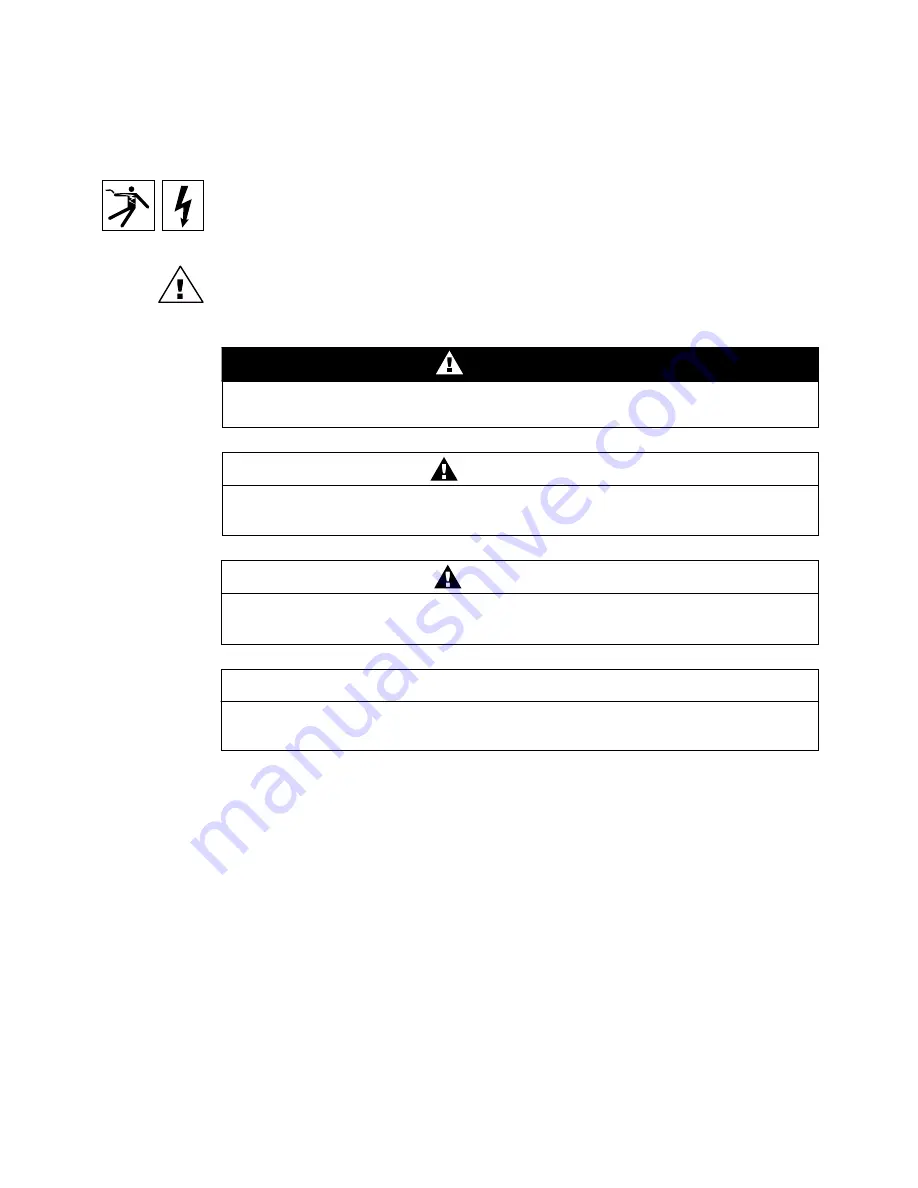
The addition of either symbol to a “Danger” or “Warning” safety label indicates that an
electrical hazard exists which will result in personal injury if the instructions are not
followed.

This is the safety alert symbol. It is used to alert you to potential personal injury
hazards. Obey all safety messages that follow this symbol to avoid possible injury or
death. CAUTION, used without the safety alert symbol, indicates a potentially
hazardous situation which, if not avoided,

can result

in property damage.

NOTE: Provides additional information to clarify or simplify a procedure.

PLEASE NOTE

This electrical equipment should be serviced only by qualified personnel. No
responsibility is assumed by Schneider Electric for any consequences arising out of
the use of this material. This document is not intended as an instruction manual for
untrained persons.

CLASS A FCC STATEMENT

This equipment has been tested and found to comply with the limits for a Class A digital
device, pursuant to part 15 of the FCC Rules. These limits are designated to provide
reasonable protection against harmful interference when the equipment is operated in
a commercial environment. This equipment generates, uses, and can radiate radio
frequency energy and, if not installed and used in accordance with the instruction
manual, may cause harmful interference to radio communications. Operation of this
equipment in a residential area is likely to cause harmful interference in which case the
user will be required to correct the interference at his own expense.

DANGER

DANGER indicates an imminently hazardous situation which, if not avoided,

will

result

in death or serious injury.

WARNING

WARNING indicates a potentially hazardous situation which, if not avoided,

can

result

in death or serious injury.

CAUTION

CAUTION indicates a potentially hazardous situation which, if not avoided,

can

result

in minor or moderate injury.

CAUTION

CAUTION, used without the safety alert symbol, indicates a potentially hazardous
situation which, if not avoided,

can result

in property damage.

© 2001 Schneider Electric All Rights Reserved

Summary of Contents for EGX200

Page 1: ...POWERLOGIC Ethernet Gateway EGX200 Retain for future use 63230 314 200 A2 8 2001 Instruction Bulletin...

Page 2: ...erial This document is not intended as an instruction manual for untrained persons CLASS A FCC STATEMENT This equipment has been tested and found to comply with the limits for a Class A digital device...

Page 3: ...T 7 EGX200 INITIAL SETUP 8 Setup Using a Web Browser 8 Setup Using HyperTerminal 13 Accessing the EGX200 Setup Utility 13 CHAPTER 4 INSTALLATION AND WIRING 17 CHAPTER CONTENTS 17 MOUNTING LOCATIONS AN...

Page 4: ...WORK 29 Logging into the EGX200 29 EGX200 EMBEDDED WEB PAGE OPTIONS 31 Communications Settings 31 Ethernet Port Setup via LAN 32 Serial COM Port Setup 32 Device List 32 Diagnostics 35 Password Adminis...

Page 5: ...IC system see the following documents POWERLOGIC System Manager SMS Software User s Guide POWERLOGIC System Architecture and Application Guide PRODUCT DESCRIPTION The POWERLOGIC EGX200 is an Ethernet...

Page 6: ...rnet and serial communication parameters A typical application example is shown in Figure 1 1 Figure 1 1 System architecture example showing EGX200 installed for Ethernet connectivity POWERLOGIC Syste...

Page 7: ...provided for installation and operation of the EGX200 EGX200 unit with all connectors plugged in 24 Vdc switching power supply wall mountable with global plug kit EGX200 mounting kit containing rubbe...

Page 8: ...or MODBUS daisy chained devices 7 Power LED This green LED illuminates steadily when minimum control power is applied to the unit 8 COM 1 LEDs The yellow LED illuminates when COM 1 is receiving data...

Page 9: ...power Assume that all circuits are live until they have been completely de energized tested and tagged Pay particular attention to the design of the power system Consider all sources of power includin...

Page 10: ...6 2001 Schneider Electric All Rights Reserved Chapter 2 Safety Precautions 63230 314 200 A2 8 2001...

Page 11: ...as the initial instructions for setting up the EGX200 before installation EGX200 QUICK START CHECKLIST Use the steps in Table 3 1 as a quick start checklist for the EGX200 For complete instructions re...

Page 12: ...ask default address 255 255 255 0 that can be used to access these web pages The Communication Settings web page is used to set up the desired IP address subnet mask and router IP address to match the...

Page 13: ...t mask 255 255 255 0 An example using Microsoft Windows NT is shown in the following substeps For help with other systems contact your network administrator a From your PC s task bar Click Start Setti...

Page 14: ...ess and Subnet Mask e From the Microsoft TCP IP Properties dialog box select Specify a IP address f Enter the IP address 10 10 10 11 and subnet mask 255 255 255 0 and then click OK g Reboot your PC if...

Page 15: ...ys as shown in Figure 3 5 Figure 3 5 EGX200 Login page 6 From the Language pull down menu select the desired language 7 In the Password field type admin 8 Click Log In The EGX200 Home page displays as...

Page 16: ...gs page displays as shown in Figure 3 7 Figure 3 7 Communications Settings page 10 Enter your IP Address Subnet Mask and Router IP address and click Update 11 Reset your PC back to its original networ...

Page 17: ...or Accessing the EGX200 Setup Utility To access the EGX200 setup utility follow these steps 1 Attach a null modem cable between the RS 232 COM port COM 2 of the EGX200 and a Microsoft Windows based PC...

Page 18: ...s shown in Figure 3 9 Figure 3 9 HyperTerminal Connection Description dialog box 3 In the Name field enter a descriptive name for your new HyperTerminal connection and then click OK The Connect To dia...

Page 19: ...ties page displays as shown in Figure 3 11 Figure 3 11 HyperTerminal COM Port Properties dialog box 5 In this dialog box set the values listed in Table 3 3 You are now ready to enter the EGX200 setup...

Page 20: ...ED is OFF press Enter The EGX200 Setup Utility menu displays as shown in Figure 3 12 Table 3 4 provides descriptions of each menu option Figure 3 12 EGX200 HyperTerminal Setup Utility options You are...

Page 21: ...and Termination 26 RS 485 Configuration 26 4 Wire Configuration 26 2 Wire Configuration 26 Ethernet Ports 27 Ethernet LEDs 27 MOUNTING LOCATIONS AND INSTALLATION The EGX200 is designed to be set on a...

Page 22: ...Installation 8 2001 Dimensions Figure 4 1 shows the EGX200 dimensions including the DIN rail mounting equipment Figure 4 1 EGX200 Dimensions 7 88 201 1 77 45 3 05 78 1 07 28 1 07 28 0 40 11 7 88 201 0...

Page 23: ...ting Options Figures 4 2 4 3 and 4 4 illustrate some of the various mounting options Wall Panel Mounting Figure 4 2 Wall Panel Mounting Template Panel Pan head screw 6 32 4 mm Panel 036 in 1 mm min 04...

Page 24: ...l Rights Reserved Chapter 4 Installation and Wiring 63230 314 200 A2 Mounting Locations and Installation 8 2001 DIN Rail Mounting Figure 4 3 DIN Rail Mounting Flat Surface Mounting Figure 4 4 Feet Ins...

Page 25: ...re is connected to the negative terminal If needed another power supply or cord can be used to power the EGX200 as long as it is rated for a minimum of 8 watts at 24 Vdc 10 regulation Figure 4 5 Contr...

Page 26: ...COM 2 please refer to the Communications Settings web page on page 31 Each port is designed to support up to a maximum of 32 devices without a repeater see Figure 4 6 The RS 485 ports enable communic...

Page 27: ...om terminal Tx to terminal Rx and another jumper wire from terminal Tx to terminal Rx Connect the shield wire to the shield terminal as shown Figure 4 9 Communications wiring 2 wire Belden 9841 cable...

Page 28: ...000ft 3 048m 4 000ft 1 219m 19200 5 000ft 1 524m 2 500ft 762m 38400 5 000ft 1 524m 1 500ft 457m Due to the volume of RS 485 devices in the field this table is only to be used as a guide and was tabula...

Page 29: ...minates when the corresponding COM port is receiving data Rx A green LED illuminates when data on the corresponding COM port is transmitted Tx Also above the COM 2 Rx and Tx LEDs a third LED green ill...

Page 30: ...last device on the daisy chain to determine whether a terminator is required If one is required contact your local sales representative 4 Wire Configuration For RS 485 4 wire configuration the biasin...

Page 31: ...have a characteristic impedance of 100 ohms and meet the EIA TIA Category 5 standard wiring specifications The cable can be either shielded twisted pair or unshielded twisted pair Ethernet LEDs The 1...

Page 32: ...28 2001 Schneider Electric All Rights Reserved Chapter 4 Installation and Wiring 63230 314 200 A2 Wiring Connections 8 2001...

Page 33: ...ed Setup 38 Logging Out 38 ACCESSING THE EGX200 OVER A NETWORK This section tells how to access the EGX200 over a network or the Internet After you set up Ethernet parameters using HyperTerminal or a...

Page 34: ...of the four defined passwords and then click Log In See Password Administration on page 36 for more information NOTE The default password is admin all lower case For system security if you are the ad...

Page 35: ...and the new settings go into effect Because of this reset you must log in to the EGX200 again by typing the IP address into the address field of your web browser and pressing Enter Figure 5 4 Communi...

Page 36: ...ther your daisy chain is 2 wire or 4 wire These ports are configured independently from each other and can have different settings In addition COM 2 can be set for either RS 232 or RS 485 communicatio...

Page 37: ...mn enter the device Address and Protocol type of each device on the daisy chain of the COM 1 port 2 Click Update COM 1 3 In the COM 2 column enter the device Address and Protocol type of each device o...

Page 38: ...GIC protocol device on a mixed mode daisy chain for example CM2000 CM100 CM200 810 D PIF85 PIF3 Digital Relay and POWERLINK AS Do not use the same address for any two devices on the two ports We recom...

Page 39: ...This page also contains information about your specific EGX200 including the serial number manufacturing date and Media Access Control MAC address Pressing Reset clears all cumulative counters The Use...

Page 40: ...always grants the administrator full access to every web page available through the EGX200 When you log in as the administrator you can change the administrator password Only the administrator can acc...

Page 41: ...user The administrator can disable the password for any page Disabling security for a page allows users to bookmark the page for quick access without going through the Login page Table 5 4 summarizes...

Page 42: ...ng Out To log out of the EGX200 configuration session click Home to return to the EGX200 Home page Click Log Out to end your session Table 5 5 Advanced communication setup parameters Parameter Range o...

Page 43: ...ure the proper cable is used and connected SMS does not connect to the EGX200 Incorrect IP address Enter correct IP address Incorrect subnet mask or IP router address Enter correct subnet mask and or...

Page 44: ...40 2001 Schneider Electric All Rights Reserved Appendix A Maintenance and Troubleshooting 63230 314 200 A2 Troubleshooting 8 2001...

Page 45: ...GX200 follow these steps NOTE In this example we will assume that you saved the EGX200 new firmware update file into a folder called EGX which is located on your C drive 1 Access DOS on your computer...

Page 46: ...password until the administrator changes it Figure B 3 Password prompt 7 At the ftp prompt Figure B 4 type send egx bin and press Enter to initiate the ftp transfer The filename you enter is case sens...

Page 47: ...nch SMS 2 Open an existing system or create a new system 3 Add a communication connection for the EGX200 For the communications connection name type a unique name for your EGX200 connection For the co...

Page 48: ...44 2001 Schneider Electric All Rights Reserved Appendix C Communicating with SMS Using the EGX200 63230 314 200 A2 8 2001...

Page 49: ...ns Length 7 88 in 200 2 mm Width 4 81 in 122 2 mm Depth 1 07 in 27 2 mm REGULATORY STANDARDS COMPLIANCE Electromagnetic Interference Radiated Emissions EN 55022 FCC Class A Conducted Emissions EN 5502...

Page 50: ...46 2001 Schneider Electric All Rights Reserved Appendix D Specifications 63230 314 200 A2 8 2001...

Page 51: ...EGX200 3 C cable Ethernet cross over 8 null modem 13 clock EGX200 38 COM 1 LED 25 COM 2 LED 25 COM port RS 232 4 RS 485 4 COM port timeout 38 command prompt 41 communications 2 wire 23 4 wire 23 sett...

Page 52: ...on 36 service 39 setup utility 16 specifications 45 time and date 38 timing values 38 using SMS 43 wiring 21 Ethernet communications setup parameters 8 cross over cable 8 LEDs 27 link LED 4 port setup...

Page 53: ...tup 32 parity setting 15 32 password administration 36 password entering 11 pinout RS 232 25 port 10 100base T twisted pair 4 com 1 25 com 1 RS 485 4 com 2 25 com 2 RS 485 4 Ethernet 4 27 Ethernet set...

Page 54: ...9 stop bits setting 15 subnet mask 9 setting 8 switches dip switch settings 4 T technical support 39 terminal block connector 21 termination 2 wire configuration 26 4 wire configuration 26 RS 485 dais...

Page 55: ......

Page 56: ...Ethernet Gateway EGX200 for POWERLOGIC Systems Bulletin No 63230 314 200 A2 Class 3020 SS 5C 8 2001...

Reviews: