background image

PH4000Ri/E Owner’s Manual

46

13. 

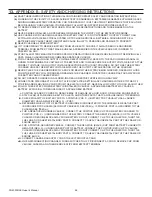
APPENDIX B - SAFETY AND CHARGING INSTRUCTIONS

(a) 

SAVE THESE INSTRUCTIONS. THIS MANUAL CONTAINS IMPORTANT SAFETY AND OPERATING INSTRUCTIONS.

(b) 

WORKING IN THE VICINITY OF A LEAD-ACID BATTERY IS DANGEROUS. BATTERIES GENERATE EXPLOSIVE GASES 

DURING NORMAL BATTERY OPERATION. FOR THIS REASON IT IS OF THE UTMOST IMPORTANCE THAT EACH TIME 

BEFORE USING YOUR CHARGER, YOU READ AND FOLLOW THE INSTRUCTIONS PROVIDED EXACTLY.

(c) 

TO REDUCE RISK OF BATTERY EXPLOSION, FOLLOW THESE INSTRUCTIONS AND THOSE MARKED ON THE 

BATTERY.

(d) 

NEVER SMOKE OR ALLOW AN OPEN SPARK OR FLAME IN THE VICINITY OF THE BATTERY OR ENGINE.

(e) 

USE CHARGER FOR CHARGING A LEAD-ACID BATTERY ONLY. IT IS NOT INTENDED TO SUPPLY POWER TO AN 

EXTRA-LOW-VOLTAGE ELECTRICAL SYSTEM OR TO CHARGE DRY-CELL BATTERIES. CHARGING DRY-CELL 

BATTERIES MAY CAUSE THEM TO BURST AND CAUSE INJURY TO PERSONS AND DAMAGE TO PROPERTY.

(f) 

NEVER CHARGE A FROZEN BATTERY.

(g) 

IF IT IS NECESSARY TO REMOVE BATTERY FROM VEHICLE TO CHARGE IT, ALWAYS REMOVE GROUNDED 

TERMINAL FROM BATTERY FIRST. MAKE SURE ALL ACCESSORIES IN THE VEHICLE ARE OFF IN ORDER TO 

PREVENT AN ARC.

(h) 

STUDY ALL BATTERY MANUFACTURER’S SPECIFIC PRECAUTIONS SUCH AS REMOVING OR NOT REMOVING CELL 

CAPS WHILE CHARGING AND RECOMMENDED RATES OF CHARGE.

(i) 

FOR A CHARGER HAVING AN OUTPUT VOLTAGE SELECTOR SWITCH, REFER TO THE CAR OWNER’S MANUAL IN 

ORDER TO DETERMINE THE VOLTAGE OF THE BATTERY AND TO MAKE SURE THE OUTPUT VOLTAGE IS SET AT THE 

CORRECT VOLTAGE. IF AN OUTPUT VOLTAGE SELECTOR SWITCH IS NOT PROVIDED, DO NOT USE THE BATTERY 

CHARGER UNLESS THE BATTERY VOLTAGE MATCHES THE OUTPUT VOLTAGE RATING OF THE CHARGER.

(j) 

NEVER PLACE THE CHARGER DIRECTLY ABOVE OR BELOW THE BATTERY BEING CHARGED; GASES OR FLUIDS 

FROM THE BATTERY WILL CORRODE AND DAMAGE THE CHARGER. LOCATE THE CHARGER AS FAR AWAY FROM 

THE BATTERY AS DC CABLES PERMIT.

(k) 

DO NOT OPERATE CHARGER IN A CLOSED-IN AREA OR RESTRICT VENTILATION IN ANY WAY.

(l) 

CONNECT AND DISCONNECT DC OUTPUT CLIPS ONLY AFTER SETTING ANY CHARGER SWITCHES TO THE OFF 

POSITION AND REMOVING AC CORD FROM THE ELECTRIC OUTLET. NEVER ALLOW CLIPS TO TOUCH EACH OTHER.

(m) 

FOLLOW THESE STEPS WHEN BATTERY IS INSTALLED IN VEHICLE. A SPARK NEAR BATTERY MAY CAUSE A 

BATTERY EXPLOSION. TO REDUCE RISK OF A SPARK NEAR BATTERY:

i. 

POSITION AC AND DC CORDS TO REDUCE RISK OF DAMAGE BY HOOD, DOOR, OR MOVING ENGINE PARTS;

ii. 

STAY CLEAR OF FAN BLADES, BELTS, PULLEYS, AND OTHER PARTS THAT CAN CAUSE INJURY TO PERSONS;

iii. 

CHECK POLARITY OF BATTERY POSTS. A POSITIVE (POS, P, +) BATTERY POST USUALLY HAS A LARGER 

DIAMETER THAN A NEGATIVE (NEG, N, –) POST;

iv. 

DETERMINE WHICH POST OF BATTERY IS GROUNDED (CONNECTED) TO THE CHASSIS. IF NEGATIVE POST 

IS GROUNDED TO CHASSIS (AS IN MOST VEHICLES), SEE ITEM (v). IF POSITIVE POST IS GROUNDED TO THE 

CHASSIS, SEE ITEM (vi);

v. 

FOR A NEGATIVE-GROUNDED VEHICLE, CONNECT THE POSITIVE (RED) CLIP FROM BATTERY CHARGER TO 

POSITIVE (POS, P, +) UNGROUNDED POST OF BATTERY. CONNECT THE NEGATIVE (BLACK) CLIP TO VEHICLE 

CHASSIS OR ENGINE BLOCK AWAY FROM BATTERY. DO NOT CONNECT CLIP TO FUEL INJECTOR, THROTTLE, 

FUEL LINES, OR SHEET-METAL BODY PARTS. CONNECT TO A HEAVY GAUGE METAL PART OF THE FRAME OR 

ENGINE BLOCK;

vi. 

FOR A POSITIVE-GROUNDED VEHICLE, CONNECT THE NEGATIVE (BLACK) CLIP FROM BATTERY CHARGER TO 

NEGATIVE (NEG, N, –) UNGROUNDED POST OF BATTERY. CONNECT THE POSITIVE (RED) CLIP TO VEHICLE 

CHASSIS OR ENGINE BLOCK AWAY FROM BATTERY. DO NOT CONNECT CLIP TO FUEL INJECTOR, THROTTLE, 

FUEL LINES, OR SHEET-METAL BODY PARTS. CONNECT TO A HEAVY GAUGE METAL PART OF THE FRAME OR 

ENGINE BLOCK;

vii. 

CONNECT CHARGER AC SUPPLY CORD TO ELECTRIC OUTLET; AND

viii. 

WHEN DISCONNECTING CHARGER, TURN SWITCHES TO OFF, DISCONNECT AC CORD, REMOVE CLIP FROM 

VEHICLE CHASSIS, AND THEN REMOVE CLIP FROM BATTERY TERMINAL.

Summary of Contents for PH4000Ri/E

Page 1: ...POWERHOUSE PH4000Ri E Electronic Fuel Injected Digital Inverter Generator Owner s Manual PLEASE READ THIS MANUAL CAREFULLY BEFORE USING...

Page 2: ...door and connect the quick connect cable to the battery wiring harness Refer to Connecting The Battery for more information 3 Replace the maintenance door 4 Connect an external battery charger such as...

Page 3: ...three seconds to allow the fuel pressure to build and the throttle valve to close iv Push the start button on the remote and hold until the engine has started or for a maximum of 10 seconds Release a...

Page 4: ...Part 15 of the FCC Rules These limits are designed to provide reasonable protection against harmful interference in a residential installation This equipment generates uses and can radiate radio frequ...

Page 5: ...rranty powerhouse products com or send a fax to 1 855 242 8922 Failure to properly follow these precautions can result in property damage serious injury or DEATH Read all labels and the owner s manual...

Page 6: ...plication 23 6 11 Generator Overload 24 6 12 Overspeed Protection 24 6 13 DC Application 25 6 13 1 Charging External Batteries 25 6 13 2 Powering 12V DC devices 26 6 13 3 Back charging the generator b...

Page 7: ...des increased efficiency over carbureted fuel systems In a carbureted fuel system the fuel and air are mixed in a carburetor that relies on a mechanical choke system controlling the rate of air intake...

Page 8: ...il tight For safety reasons it is better to shut the generator down before moving it You should also unplug all cords connected to the generator to prevent a tripping hazard and or damage to the cords...

Page 9: ...amage and or severe personal injury or death may result Never connect this generator to an automatic transfer switch ATS Severe damage to the generator will occur Never connect this generator to an au...

Page 10: ...wner s Manual 10 4 Component identification 4 1 PH4000Ri E Generator Control panel Gas gauge Gas cap Starter grip Engine oil access door Pneumatic tire Maintenance door Stabilizing rubber feet Telesco...

Page 11: ...OTTANT SYSTEM FLOATING RESEAU FLOTTANT Digital display Ignition switch Fault code button 120 V circuit breakers 120 V duplex receptacle Stop button red Ground terminal 120 V locking receptacle Low oil...

Page 12: ...enerator toward the muffler grill close to the bottom 2 On the back of this owner s manual You can also find the BCN number on the foil label on the shipping carton Please record this information belo...

Page 13: ...es below 32 F You can use synthetic oil the first time you fill the oil well of your generator and you can use it for subsequent oil changes 1 Loosen the oil access cover screw and remove the cover 2...

Page 14: ...operly and securely Be careful not to spill fuel when refueling Spilled fuel or fuel vapor may ignite If any fuel is spilled make sure the area is dry before starting the engine Avoid repeated or prol...

Page 15: ...to connect the battery before you begin using the generator Due to the nature of lead acid batteries it may be necessary to charge the battery before using the generator the first time or after long t...

Page 16: ...reported by a sensor These shutdowns may occur when you are not present When the generator engine shuts off there will still be a drain on the battery due to the display the ECU and the stepper motor...

Page 17: ...of how you start the unit If the battery charge is just high enough to run the fuel pump and the ECU the generator can be started by recoil but not by the ignition key or remote You must either charg...

Page 18: ...using the remote function 1 Move the remote selector switch on the control panel to the ON position 2 Push the start button on the remote twice and hold while the engine cranks 2 3 times without start...

Page 19: ...erator is 0 to 113 F 18 to 45 C Although the generator can operate at 0 F 18 C it will be necessary to use a lower viscosity engine oil such as SAE 0W 40 Synthetic oil is recommended for temperatures...

Page 20: ...receptacle Do not connect the generator to a household circuit This could cause damage to the generator or to electrical appliances in the house Do not modify or use the generator for purposes other...

Page 21: ...lay will not illuminate unless the generator is started It is normal for the run time indicator to have 1 2 hours on the meter from the factory for testing and quality assurance inspections The digita...

Page 22: ...ection of this manual When the Low Oil indicator blinks repeatedly press the fault code button on the top right of the digital display The display will cycle through the fault codes in the Wattage P d...

Page 23: ...is illuminated and returning data 3 Confirm that the appliance to be used is switched off before plugging into the control panel 4 Plug the appliance into the control panel Be sure that all appliance...

Page 24: ...t exceed that of the generator 6 12 Overspeed Protection This generator has been designed to prevent the engine from overspeed revving Overspeed revving occurs when a generator s on board monitoring s...

Page 25: ...cord to the positive battery terminal Do not reverse the charging cables or serious damage to the generator and or battery may occur Physical injury may also occur Do not attempt to start an automobi...

Page 26: ...re are no special considerations for switches to be on or off for the battery to charge though if the generator is not running the remote switch should be in the OFF position The ECU and fuel pump req...

Page 27: ...codes section of this manual for more information 6 15 Stopping the engine To stop the engine in an emergency 1 Push the STOP button on the control panel This will stop the unit with or without the i...

Page 28: ...as started and is performing normally It is also important to follow the air conditioner manufacturer s instructions for starting and restarting for proper operation Some air conditioner manufacturers...

Page 29: ...standards regarding the emission control system Tune up specifications are provided in the Specifications section and a description of the emission control system may be found in the appendix to this...

Page 30: ...o compare the emission performance of different engines The lower the air index the better the engine emission performance The description of durability is helpful for the user to learn the engine emi...

Page 31: ...ine Check Every 2 years Replace as necessary 3 Battery Clean Charge Charge monthly during long term storage Check terminals for corrosion monthly clean as needed Expected battery life is 2 years but c...

Page 32: ...dipstick 6 Reinstall the oil access cover and tighten the screw securely Recommended oil is SAE 10W 30 or 15W 30 when ambient temperature is above 32 F 0 C SAE 0W 30 or 0W 40 is recommended if operati...

Page 33: ...id engine wear may result 1 Loosen the cover screws and remove the maintenance door 2 Remove the cartridge retaining screws Remove the cartridge and check the element Clean or replace the element if n...

Page 34: ...y carefully bending the side electrode 9 Install the spark plug carefully by hand to avoid cross threading 10 After a new spark plug has been seated by hand it should be tightened 1 2 turn with a wren...

Page 35: ...ff the grill This will not cause an issue unless you drop the arrester or the clamp or screws behind the grill Taking the grill off or leaving it on is a matter of your convenience but the procedure b...

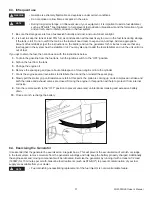
Page 36: ...nerator while it is on or in a vehicle If you must transport the generator in an enclosed vehicle drain all fuel from the generator 8 2 Short term storage of the Generator During short term storage th...

Page 37: ...ignition switch to the OFF position 4 Siphon the fuel from the tank 5 Change the engine oil 6 Remove the spark plug and pour about a tablespoon of clean engine oil into the cylinder 7 Crank the engin...

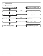
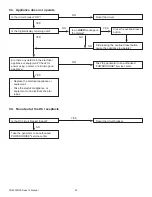
Page 38: ...rator and retry Is the key fob battery drained Replace the key fob battery Is the remote switch turned off Turn on the remote switch Is the battery fuse missing or burned out Is the battery dead Check...

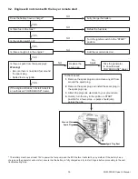
Page 39: ...on switch on Turn the ignition switch to the START position Is there enough oil in the engine Add the recommended oil Is there a spark from the spark plug Warning Be sure there is no spilled fuel arou...

Page 40: ...or equipment Check for power using a meter or a known good appliance Did pressing the overload reset button cause the appliance to operate Replace the electrical appliance or equipment Take the elect...

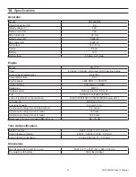
Page 41: ...F7RTC Starting system Remote Electric Recoil Fuel Automotive unleaded gasoline Lube oil synthetic or conventional SAE 10W 30 15W 30 0W 30 0W 40 below 32 F Oil Capacity 33 8 fl oz 1 0 L Fuel tank capa...

Page 42: ...r or replace any part or unit at its option Coast Distribution may request defective parts to be returned Anything replaced under warranty becomes the property of Coast Distribution To Obtain Warranty...

Page 43: ...ystem is warranted for two years If any emissions related part on your engine is defective the part will be repaired or replaced by Coast Distribution System Inc Owner s Warranty Responsibilities As t...

Page 44: ...injector system Engine speed control system ECU Intake manifold Engine control module Evaporative Control System Fuel tank Fuel cap Fuel strainer Fuel injector Fuel pump Fuel lines Carbon canister in...

Page 45: ...k cap indicator and hoses are specially designed and constructed to not allow fuel vapors to permeate and be released to the atmosphere 2 A carbon activated canister collects gasoline vapors from the...

Page 46: ...E AND DAMAGE THE CHARGER LOCATE THE CHARGER AS FAR AWAY FROM THE BATTERY AS DC CABLES PERMIT k DO NOT OPERATE CHARGER IN A CLOSED IN AREA OR RESTRICT VENTILATION IN ANY WAY l CONNECT AND DISCONNECT DC...

Page 47: ...HEN CONNECT THE NEGATIVE BLACK CHARGER CLIP TO FREE END OF CABLE v DO NOT FACE BATTERY WHEN MAKING FINAL CONNECTION vi CONNECT CHARGER AC SUPPLY CORD TO ELECTRICAL OUTLET AND vii WHEN DISCONNECTING CH...

Page 48: ...7930 S W Burns Way Unit C Wilsonville OR 97070 www powerhouse products com This manual version applies to BCNs equal to or greater than 140915415155001 PH4000Ri E Owner s Manual Revision 2014 08 27 BC...

Reviews: