background image

Page 

42

 of 

80 

Instruction Manual for AURORA CDD 

BCG.00613_AA


Part

 4 

Operations Guide 


4.3


REMOTE MONITORING ON THE AURORA EASY VIEW PORTAL 

Once the acquisition of the MICRO Inverters is complete, it is possible to configure the remote 

monitoring of the plant on the Aurora Vision web portal using the 

Self Registration 

procedure 

(through the Power- One website). 


For installers with an Aurora Vision account who want to manage their costumer account 

please refer to the documentation on 

www.auroravision.net


4.3.1


“S

ELF

-R

EGISTRATION

 PROCEDURE


Homeowners can register their plant through the Power-One Website (no special customer or user 

account is necessary). At the end of the registration process, an Aurora Easy View account will be 

created for the homeowner giving them 100% control of their web-based monitoring solution. 


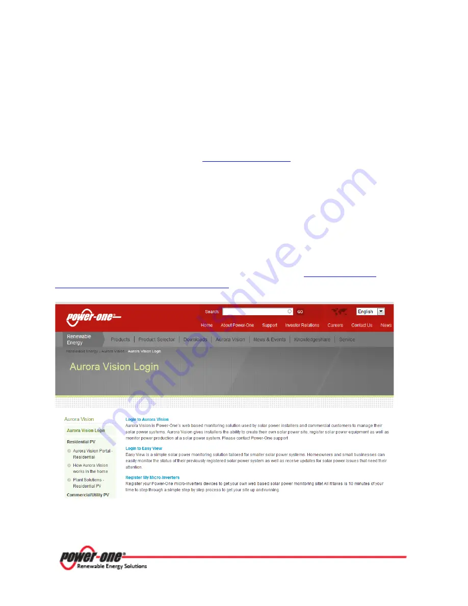
To start the self-registration process, go to the Power-One website at 

http://www.power-

one.com/renewable-energy/aurora-vision-login

 and select “Register My Micro-Inverters”. 


This web page will be accessed again to “

Login to Easy View”

 using the account created in the 

registration process. 

Summary of Contents for Aurora CCD

Page 1: ...THE MANUAL AURORA CDD...

Page 2: ...Page 1 of 80 Instruction Manual for AURORA CDD BCG 00613_AA AURORA CDD Concentrator Data Device Instruction Manual...

Page 3: ...or consequential damages under any circumstances Power One Renewable Energy Solutions LLC reserves the right to make changes to this document without notice and shall not be responsible for any damage...

Page 4: ...HE CDD 19 3 3 CABLED CONNECTION ETHERNET 21 3 4 WIRELESS CONNECTION WIFI 26 PART 4 OPERATIONS GUIDE 33 4 1 GENERAL CONDITIONS 34 4 2 COMMISSIONING 34 4 3 REMOTE MONITORING ON THE AURORA EASY VIEW PORT...

Page 5: ...Page 4 of 80 Instruction Manual for AURORA CDD BCG 00613_AA PART 1 INTRODUCTION AND SAFETY...

Page 6: ...CDD Concentrator Data Device and carry out the operations necessary for keeping the equipment in good working order 1 2 2 TARGET GROUP The installation is to be done by qualified installers a license...

Page 7: ...he following information Figure 1 1 AURORA CDD Nameplate Besides the label showing the CDD nameplate data an additional product identification label is also present The label displays the following in...

Page 8: ...r television reception which can be determined by turning the equipment OFF and ON the user is encouraged to try to correct the interference by one or more of the following measures Re orient or reloc...

Page 9: ...e reader should stop use caution and fully understand the operations explained before proceeding UL60950 1 Safety of Information Technology Equipment General Requirements Part 1 CSA 60950 1 07 Safety...

Page 10: ...The equipment must not be used in a ways that do not fall within the intended field of use 1 3 2 1 Intended or Allowed Use This equipment is a device designed to configure and control a network of Po...

Page 11: ...ing the equipment or its parts without having read and correctly interpreted the contents of the operating and maintenance manual 1 3 3 SAFETY INSTRUCTIONS The equipment has been manufactured in accor...

Page 12: ...onnected electrical devices from lighting to household appliances etc When the photovoltaic system is not supplying sufficient power the power needed to ensure normal operation of the connected electr...

Page 13: ...and intuitive use with the option of navigating through the various menus by means of buttons on the side of the CDD 1 4 4 OPERATING DIAGRAM The diagram for this system shows how several wireless Pow...

Page 14: ...Page 13 of 80 Instruction Manual for AURORA CDD BCG 00613_AA PART 2 UNPACK AND SELECT INSTALLATION LOCATION...

Page 15: ...ndition of the unit shipped Upon receipt of AURORA CDD please perform the following check Inspect the shipping container for any external damage Inventory the contents against the listing below and ve...

Page 16: ...ach of the device as noted below Table 2 2 Factors affecting wireless signal strength Material Relative signal range reductions Open Field Approximately 100 m Wood Glass 0 10 Stone Pressed cardboard 1...

Page 17: ...ocation 2 2 1 2 Point the Radio Antenna In order to boost the signal strength point the antenna of the CDD in a parallel line to the MICRO Inverters as shown below Figure 2 2 Optimal CDD signal streng...

Page 18: ...Page 17 of 80 Instruction Manual for AURORA CDD BCG 00613_AA PART 3 MOUNTING AND CONFIGURATION...

Page 19: ...e the bottom part of the device where all the connections are present see Table 3 1 remains accessible The mounting instructions are as follows and referenced in the figure below 1 Make the two holes...

Page 20: ...RESENTION OF THE CDD Figure 3 1 Graphical Representation of References Table 3 1 Reference Number Index 01 WiFi Antenna 06 Ethernet Port 02 Status LED 07 RJ45 Connector for RS485 Serial 03 RF Antenna...

Page 21: ...e around inside a menu or to scroll through a list of settable values The ESC button returns the user to the previous submenu when navigating The ENTER button is pressed to bring the user to the desir...

Page 22: ...on the CDD display at the same time and hold for 3 seconds This will bring up the Set Password message In order to enter the password of 9999 press the UP or DOWN buttons to scroll the list of charac...

Page 23: ...led connection of CDD to computer The Ethernet port is located on the lower side of the CDD In both solutions be careful not to put the Ethernet cable in the RJ45 connector for RS485 serial communicat...

Page 24: ...cannot find an IP address You will need to use the following procedure to connect Click on the Internet icon in the computer system tray When the window launches select Open Network and Sharing Center...

Page 25: ...Page 24 of 80 Instruction Manual for AURORA CDD BCG 00613_AA Part 3 Mounting and Configuration Choose Properties Click Local Area Connection...

Page 26: ...and Configuration From the list click Internet Protocol Version 4 TCP IPv4 Click the radio button next to Use the following IP address and enter a different IP address from that listed For instance i...

Page 27: ...rks the WPA and WPA 2 security protocols are supported For the configuration it is not necessary to be connected to the Internet Turn on the CDD by attaching the Power Supply connector to the bottom o...

Page 28: ...of the installation differs on the basis of the type of security of the selected network Open WPA WPA2 and on the presence or otherwise of the MAC address filter 3 4 1 1 Configuration of Open Network...

Page 29: ...If you are using a router the MAC address will be needed when setting up the configuration menu of the router The router is not supplied by Power One Refer to documentation from the manufacturer of yo...

Page 30: ...der to input the passkey press the UP or DOWN buttons to scroll the list of characters 0 9 A F and press ENTER to confirm the character selected In order to cancel the last character input press ESC P...

Page 31: ...and subsequently press UP or DOWN until the WiFi enabled Yes screen is shown Press ENTER to remove the arrow next to Yes then use the UP or DOWN button to choose the option No Press ENTER to confirm...

Page 32: ...nd network key Therefore if the automatic connection function is running the CDD will automatically connect to the WiFi network To activate deactivate the automatic connection function press ESC to ac...

Page 33: ...IP Address View With the CDD connected to the network it is possible to view the IP address assigned to the device Press ESC from the main menu and use the UP and DOWN buttons to locate the Web Serve...

Page 34: ...Page 33 of 80 Instruction Manual for AURORA CDD BCG 00613_AA PART 4 OPERATIONS GUIDE...

Page 35: ...foreign bodies Power One cannot be held responsible for damage to the equipment or the operator if it is the result of incompetence insufficient qualifications or lack of training 4 2 COMMISSIONING On...

Page 36: ...ACQUISITION OF MICRO INVERTERS Open the CDD local web server page on your browser as described in section 4 2 1 above A browser activated with JavaScript must be used in order to correctly view the L...

Page 37: ...ition Wizard requires authentication Enter the default access credentials username admin password admin Press OK After entering the username and password you will be at Step 1 of the acquisition proce...

Page 38: ...a list of the MICRO Inverters will be displayed and include the MAC RF MAC Radio Frequency Address SN Serial Number and Signal radio signal quality indicator for each inverter found There is no timeo...

Page 39: ...O Inverters with a signal less than 25 should not be assigned as they would be too weak In this case it is necessary to assess whether to install the CDD in a new position or to use a signal repeater...

Page 40: ...and the choice of 208V or 240V The CDD will set the standard selected on each of the MICRO Inverters in communication Do not set network standards that do not match those of the country of installati...

Page 41: ...13_AA Part 4 Operations Guide The last step involves registration of the CDD on the Aurora Vision web portal The link will take you to the Welcome page Click on the link to register the CDD on the Aur...

Page 42: ...r all new installations and replacement parts However you can complete the acquisition process without registering the CDD on the Aurora Vision web portal or register later by clicking on PLEASE CLICK...

Page 43: ...se refer to the documentation on www auroravision net 4 3 1 SELF REGISTRATION PROCEDURE Homeowners can register their plant through the Power One Website no special customer or user account is necessa...

Page 44: ...If you click cancel you will leave the self registration process The registration process is completed in three steps 1 Enter your personal contact information and validate your email account 2 Provid...

Page 45: ...e Step 1 To enter your personal information fill in the form The security questions may be required to log back into the site or recover your password so make sure to write them down When you complete...

Page 46: ...tart the process from Step 1 If you do not validate the account within 3 days the account will be invalidated and you will have to restart the registration process The link will take you to Step 2 for...

Page 47: ...help direct the current and future homeowners to the installer for future project and service needs Your site information defaults to the homeowner s address but can updated to a different address for...

Page 48: ...h is located on both the CDD as well as the packaging for the CDD To link the CDD A Make sure the CDD is connected to the internet B Enter the CDD s RF MAC address in the 8 display fields C Click on t...

Page 49: ...verters by the CDD the local Web Server makes it possible to monitor the whole system constantly showing the data for each individual inverter A browser activated with JavaScript must be used in order...

Page 50: ...N Part number FREQ Frequency TEMP DSP Internal DSP temperature TEMP MOSF Mosfet temperature Signal Indicates the radio communication signal between the CDD and the MICRO inverter ALARM STAT Indicates...

Page 51: ..._AA Part 4 Operations Guide 4 4 2 VIEW MENU From the menu bar click on VIEW and select the PLANT INFO option from the drop down selection This window will display all the plant data plant name place c...

Page 52: ...Inverter sends a package of data to the CDD once a minute Msg and Average plant signal index are refreshed every 15 minutes In order to evaluate a CDD positioning 15 minutes have to pass from the pow...

Page 53: ...menus Click on PLANT Selection of the option Acquisition Wizard from the Config menu is described in section 4 2 2 above and enables the CDD to acquire the MICRO Inverters Selecting Plant displays the...

Page 54: ...n Manual for AURORA CDD BCG 00613_AA Part 4 Operations Guide Select the option NETWORK from the Config menu This selection will open the configuration page with the main information on the network to...

Page 55: ...f 80 Instruction Manual for AURORA CDD BCG 00613_AA Part 4 Operations Guide Select DATE TIME from the Config menu This option displays a configuration page with fields in which you can adjust the date...

Page 56: ...RORA CDD BCG 00613_AA Part 4 Operations Guide Select CDD clone from the Config menu From this submenu a new CDD can be configured with the same settings as a previous one by inserting the last 4 pairs...

Page 57: ...ONFIG menu also allows you to change the default password which is admin To reset the password select the item CHANGE PASS from the drop down CONFIG menu A page will be displayed to create the new pas...

Page 58: ...AA Part 4 Operations Guide 4 4 4 EVENTS MENU Select the EVENTS on the main menu This selection will open a page with all the events relating to errors Exxx and alarms Wxxx in the system See Troublesho...

Page 59: ...Firmware upgrade is available in four additional areas of the CDD Select CDD RF Fw from the drop down menu to update the firmware of the CDD internal RF microprocessor Select MICROinv RF Fw from the...

Page 60: ...tional green Reporting of radio communication problems between MICRO inverters and CDD or between CDD and Router A transitional or permanent state caused by the failure to receive data by the CDD or b...

Page 61: ...ce messages for the operator View warning and breakdown messages Modify the settings of the inverter During the normal functioning of the plant the display cycles through the following information Nam...

Page 62: ...on returns the user to the previous submenu when navigating The ENTER button is pressed to bring the user to the desired submenu or to confirm an entered value parameter The UP and DOWN buttons pushed...

Page 63: ...plant is sent Primary DNS relating to the Internet Secondary DNS relating to the Internet Enables the activation or deactivation of the WiFi connection Autoconnection to the Internet Yes or No Enable...

Page 64: ...and hold the UP or DOWN button to scroll through the list of characters UP begins scrolling the characters first and then symbols and numbers with the alphabet last DOWN begins scrolling in the other...

Page 65: ...roduced from beginning of operation Enables access to the statistical data referring to the individual MICRO Inverters associated with the CDD Figure 4 4 CDD Statistics Menu Press the ENTER button in...

Page 66: ...d Input voltage DC Output voltage AC Firmware version of the DSP inside the inverter Firmware version of the MICROprocessor inside the inverter Name of the device ID MAC Address of the inverter Output...

Page 67: ...D device Press ENTER to access the four screens below Firmware version Bootloader CDD Firmware version WIFImodule CDD Firmware version radio module CDD Firmware version of the application CDD Date set...

Page 68: ...ed menu language Enables setting of the current time and date daylight saving time not included Enables setting of current time and date Enables access to setting the timeout of the display Enables se...

Page 69: ...Page 68 of 80 Instruction Manual for AURORA CDD BCG 00613_AA PART 5 TROUBLESHOOTING...

Page 70: ...a and b have been verified and the error persists the malfunction may be caused by an internal inverter fault Vbulk OV E004 The error is generated when the voltage at the ends of the bulk capacitors e...

Page 71: ...kage that prevents the grid connection of the inverter In this case the PV module must be replaced b If the measured value exceeds 1K try connecting the MICRO inverter to a different PV module If the...

Page 72: ...are performed via the Internal Web Server see the CDD manual with the software package obtained from Power One Service Vpanel Problem W001 This alarm is displayed when the input voltage generated at...

Page 73: ...ation between the CDD device and the MICRO inverters Use the CDD Internal Web Server to verify the signal quality refer to the CDD manual for information on the Internal Web Server Remote Off E035 The...

Page 74: ...Page 73 of 80 Instruction Manual for AURORA CDD BCG 00613_AA PART 6 MAINTENANCE GUIDE...

Page 75: ...estore the normal conditions correctly or otherwise make sure that this is done Power One accepts no liability if the checking and maintenance cycles indicated in this manual and in the accompanied do...

Page 76: ...s capable of communicating errors warnings via radio to the associated CDD device Any messages received and related codes can be checked on the display for the CDD device See Part 5 Troubleshooting fo...

Page 77: ...s a check and in some cases the removal of oxidation and dust that will also have settled inside the equipment if not suitably protected 6 2 2 DISMANTLING DECOMMISSIONING AND DISPOSAL Power One CANNOT...

Page 78: ...Page 77 of 80 Instruction Manual for AURORA CDD BCG 00613_AA PART 7 APPENDIX...

Page 79: ...Page 78 of 80 Instruction Manual for AURORA CDD BCG 00613_AA Part 7 Appendix 7 1 TECHNICAL DATA Table 7 1 Technical Data...

Page 80: ...Page 79 of 80 Instruction Manual for AURORA CDD BCG 00613_AA Part 7 Appendix 7 2 WIRING DIAGRAM Figure 7 1 CDD Wiring Diagram...

Page 81: ...References 19 Table 3 1 Reference Number Index 19 Figure 3 2 Cabled connection of CDD to computer 22 Table 4 1 LED behavior 59 Figure 4 1 CDD General Information Display 60 Figure 4 2 CDD Information...

Page 82: ...800 00 28 76 72 Aurora Power Service Germany 0800 2200211 Aurora Power Service Italy 00 800 00 28 76 72 Aurora Power Service Spain 00 800 00 28 76 72 Aurora Power Service Middle East 00 800 00 28 76...

Reviews: