Powered by Safety
®
48
Maintenance
PowlVac® ARG & ARM Series 4 Vacuum Circuit Breakers
5kV & 15kV - 1200A, 2000A, & 3000A - 25kA, 36kA, 50kA, & 63kA
01.4IB.60306
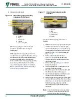
ii. If the circuit breaker did NOT
TRIP during the test performed
in
step 12
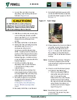
, reset the feeler gauges
with 0.030” selected and position
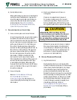
the feeler gauge as shown in
.
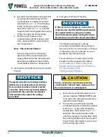
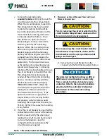
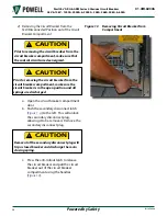
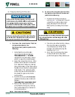
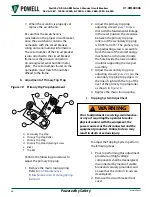
14. Slowly depress the trip coil armature
using the manual charge handle.
Position the handle as shown in
. Depress the handle until
the armature contacts the feeler
gauges. The circuit breaker should
trip.
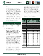
Note:
Do NOT tilt the armature. Tilting the
armature by applying a load to the
right of the feeler gauges will produce
incorrect results.
15. If the circuit breaker did not TRIP
during the test performed in
step 14
, remove the feeler gauges
and trip the breaker. Decrease the
gap between the trip coil armature
and the trip lever by bending the
trip lever upwards slightly using
channel lock pliers or a small
crescent wrench. Repeat
steps 9, 10,
and 14
.
Note:
Bend the trip lever in very small
increments. This process may take
several attempts.
16. Repeat
steps 9 through 15
until
the breaker does not trip with the
0.090” gauge inserted in the trip coil
armature gap and does trip with the
0.030” gauge inserted into the trip
coil armature gap.
17. Manually CLOSE and TRIP the circuit
breaker so that all springs are
discharged.
18. Perform the latch check switch
adjustment per the procedure found
Ch 5 Maintenance, B. Mechanism
Area, 4) Slow Closing of Mechanism,
d. Latch Check Switch Adjustment
19. Replace circuit breaker front cover.
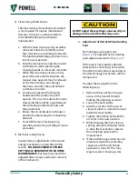
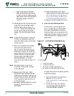
d. Latch Check Switch Adjustment
The latch check switch adjustment
) described is not required
for routine maintenance; however,
the latch check switch may need to be
adjusted after major overhaul, removal
of the mechanism, or tripping system
adjustment.
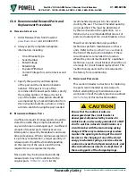
Figure 20 Latch Check Switch Adjustment
b
Pivot Screw
0.045"
a
c
d
a. Latch Check Switch
b. Latch Check Operator
c. Secondary Trip Prop Adjusting Screw
d. Secondary Trip Prop Adjusting Screw Nut
To adjust the latch check switch perform
the following steps:
1. Remove the main closing spring.
Refer to
B. Mechanism Area, 3) Closing Spring
2. Rotate the crank arms until the
spring charge indicator displays,
CLOSING SPRING CHARGED.

