Powered by Safety
®
53
Recommended Renewal Parts and Replacement Procedures
01.4IB.60306
1) Vacuum Interrupter Assembly
Refer to service manual
01.4SM.1900
Vacuum Interrupter Assembly
for
replacement and installation procedures on
circuit breakers rated up to and including
50kA.
NOTICE
For all 63kA rated circuit breakers, the
vacuum interrupter should only be replaced
by a qualified person or a Powell Service
technician. Contact Powell for further
assistance at 1.800.480.7273.
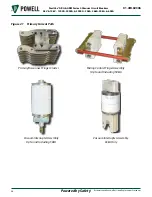
2) Sliding Contact Finger Assembly (for circuit
breaker rated up to 50kA only)
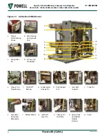
To clean, inspect, and lubricate the sliding
contact finger assemblies remove the four
sockethead screws holding the sliding
contact finger assemblies and pivot the
assemblies down. Wipe the lubrication
from the surfaces of the lower contact
block, sliding contact fingers, and the
lower primary disconnecting devices and
examine the surfaces. The sliding contact
finger locations should present a burnished
silver contact without copper appearance
at more than one location. If the copper is
visible at more than one location per pole
or silver is torn on the lower contact block
the vacuum interrupter assembly should be
replaced.
The sliding contact finger assemblies
on the PowlVac® circuit breakers are
reversible. Since only the upper ends of
the fingers experience any wiping action,
the wear is normally confined to that
end. If the upper ends of the fingers show
noticeable wear, the finger assemblies can
be reversed. Loosen the bolt holding the
rear mounting clip and remove the finger
assembly. Invert the assembly and place
it in the mounting clips. Tighten the bolt
holding the rear mounting clip. If copper
is visible at more than one contact location
on a finger assembly, that assembly
should be replaced. Apply a light coat of
B - Grease contact lubricant to both sides
of the contact blocks and to the contact
areas of the lower primary disconnecting
devices. Reassemble the sliding contact
finger assemblies by replacing the four
sockethead screws and tighten to a torque
value of 8-12 ft-lb.
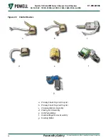
3) Closing Coil Assembly
Refer to service manual
01.4SM.1300
Closing Coil Assembly
for replacement and
installation procedures.
4) Primary Shunt Trip Coil Assembly
Refer to service manual
01.4SM.1600
Primary Shunt Trip Coil Assembly
for
replacement and installation procedures.
5) Secondary Shunt Trip Coil Assembly
Refer to service manual
01.4SM.1700
Secondary Shunt Trip Coil Assembly
for
replacement and installation procedures.
6) Undervoltage Device Assembly (UV)
Refer to service manual
01.4SM.1800C
Undervoltage Assembly
for replacement and
installation procedures.
7) Charging Motor Assembly
Refer to service manual
01.4SM.1200
Charging Motor Assembly
for replacement and installation procedures.

