


Publication No. 5102977
3
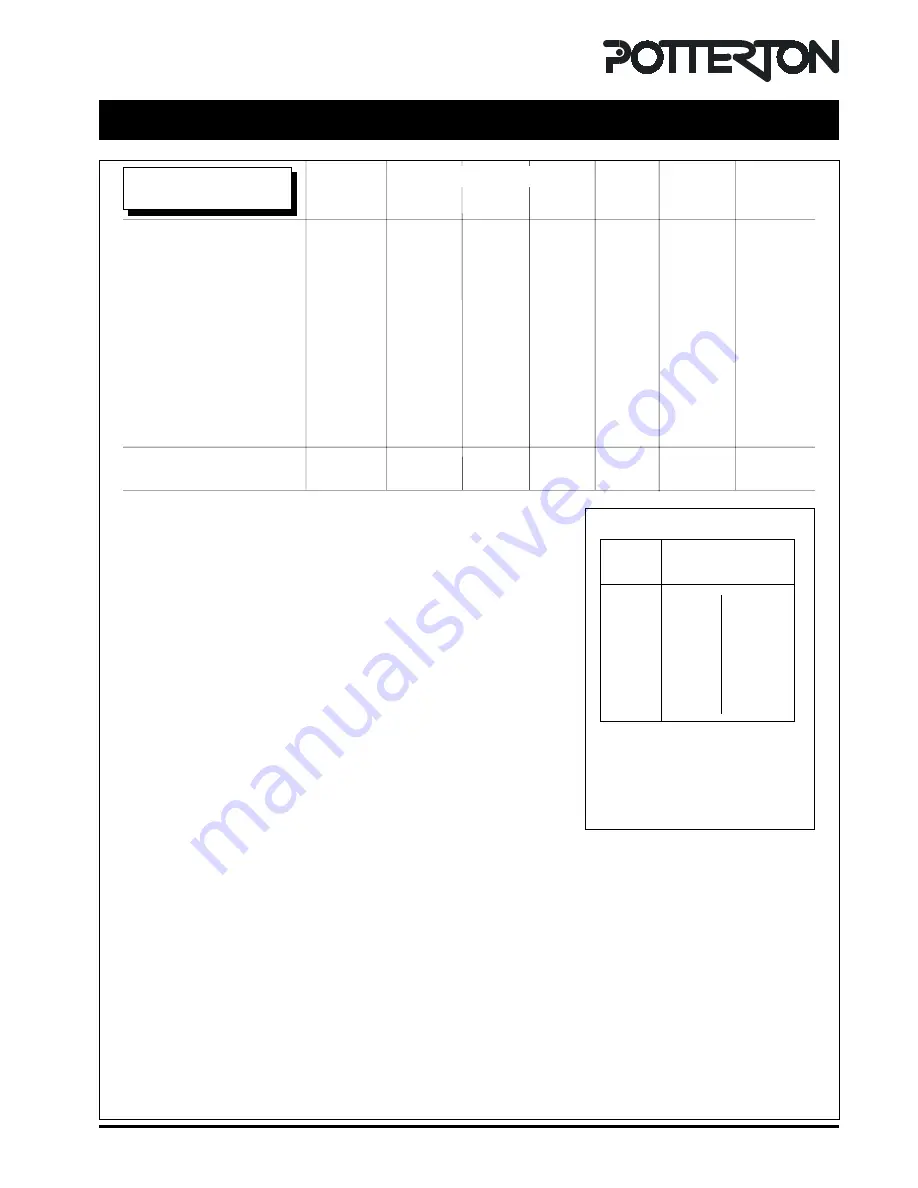
Technical Data
Technical Data
Heat Input & Efficiency
figures are quoted as gross
Boiler models
40
50
60
70
80
90
100
Maximum Rate
Output
kW
11.72
14.65
17.58
20.52
23.45
26.38
29.31
Btu/h
40,000
50,000
60,000
70,000
80,000
90,000
100,000
Input
kW
14.47
18.31
22.00
25.60
28.95
32.98
36.76
Btu/h
49,372
62,474
75,064
87,347
98,777
112,528
125,425
Gas rate
m³/h
1.38
1.75
2.10
2.44
2.76
3.14
3.50
ft³/h
48.73
61.65
73.98
86.31
97.42
110.97
123.75
Efficiency
%
81.0
80.0
80.0
80.0
81.0
80.0
79.7
Burner Pressure
mbar
13.5
14.8
11.9
12.1
11.3
13.1
13.0
in wg
5.42
5.92
4.76
4.54
4.54
5.24
5.20
Injector Size
mm
2.9
3.2
3.7
3.9
4.3
4.4
4.7
Maximum Working Head
30.5 m (3 bar)
Minimum Working Head
300 mm
Minimum Circulating Head - Gravity
1.2 m
Gas Supply Pressure
20 mbar
Gas Supply Connection
Rc. ½ (½ in BSP Female)
Maximum Flow Temperature
82 °C
Flow Connection
28 mm Copper
Return Connections - Gravity
28 mm Copper
Return Connections - Pumped
28 mm Copper
Water Content
6.5 litres
Appliance Weight Installed - Dry
65.0 kg RSL / 69.0 kg CFL
Electricity Supply
230v ~ 50Hz Fused at 3A
Internal Fuse
Type 2 AT (2 off)
Power Consumption
80 Watts (excluding pump)
Classifications
CAT I
2
H
2H G20 20 mbar
B
22,
C
12,
C
32
(40 - 70 models)
B
22,
C
12
(80 - 100 models)
IP20
NOx Class 1 - CFL90, 100 & RSL60, 70, 80, 90, 100 models
NOx Class 2 - CFL40, 60, 70, 80 & RSL40, 50 models
NOx Class 3 - CFL50 model
SEDBUK Declaration for Kingfisher
Model
Seasonal Efficiency
(SEDBUK) (%)
RSL
CFL
40
78.5
78.4
50
78.5
78.5
60
78.5
78.0
70
78.1
78.0
80
78.2
78.3
90
78.1
78.0
100
78.0
78.0
This value is used in the UK
Government's Standard Assessment
Procedure (SAP) for energy rating of
dwellings. The test data from which it
has been calculated have been certified
by 0086.
Summary of Contents for Kingfisher Mf CFL40 - 100
Page 13: ...Publication No 5102977 13 CON0093B Installation Requirements Fig 8 Fig 7 ...
Page 14: ...Publication No 5102977 14 Installation Requirements Fig 9 Fig 10 ...
Page 31: ...Publication No 5102977 31 Fig 30 Pictorial Wiring Diagram CON0082B T T B CFL Models Only ...
Page 34: ...Publication No 5102977 34 Fault Finding ...


