background image


12 

1. Product Overview 

(1) Inside Your Package 

1.


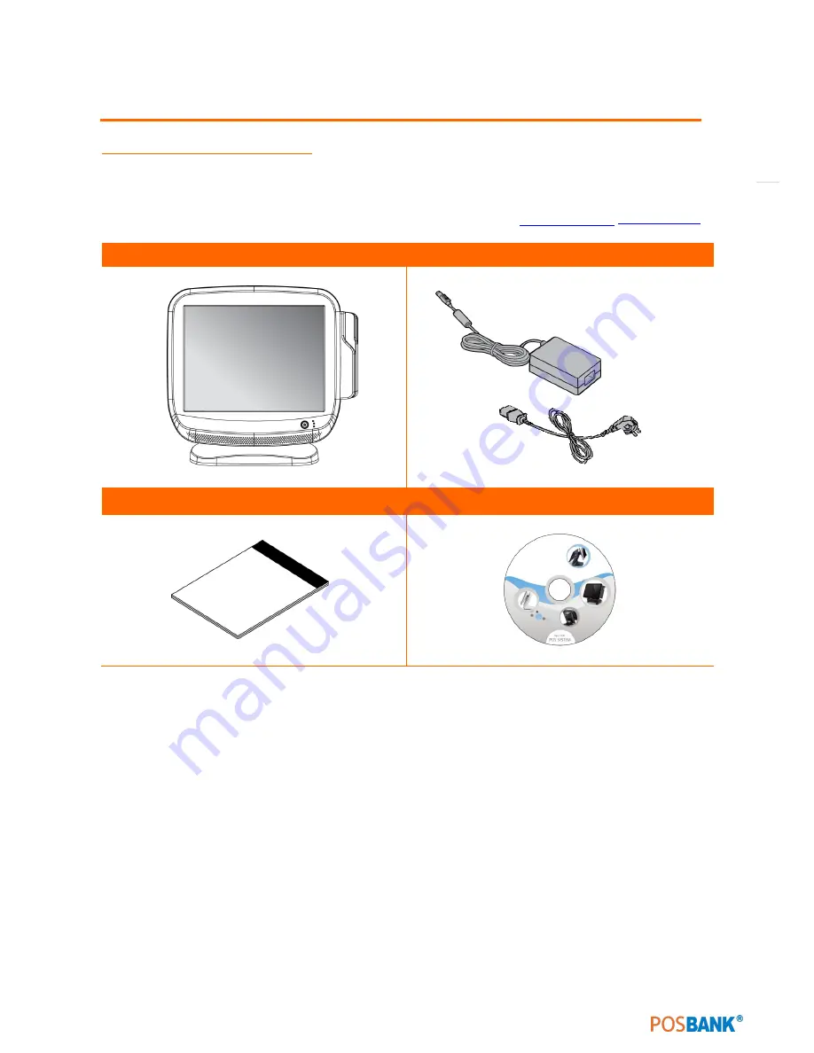
Please check your package and confirm its contents. 

2.


The POS terminal main unit, power cable, user manual and driver CD are included in the package. If any 
items are missing or damaged, please contact your dealer for assistance. 

» All user manuals and drivers are available for download on our website: 

www.posbank.com

/

www.easyset.org


AnyShop Eco Main unit 

Adapter / Power cord 


Installation guide 

Drivers CD 


Summary of Contents for AnyShop Eco

Page 1: ...Point of sale system AnyShop Eco User s manual PBUM 017E Rev004 130530...

Page 2: ...INE IN CONNECTION 25 11 SETTING UP PRINTER CONNECTION 26 12 SETTING UP POWER CABLE CONNECTION 27 13 SWITCHING ON POS 28 14 SHUTTING DOWN POS 29 15 SYSTEM DRIVERS 30 2 MOTHERBOARD 31 1 MOTHERBOARD OVER...

Page 3: ...ed to the manufacturer Neither this manual nor any of the material contained herein may be reproduced without express written consent of the author AnyShop and POSBANK are trademarks of POSBANK Co Ltd...

Page 4: ...ished replacement parts free of charge with one way shipping costs borne by the seller The customer shall however be responsible for the return delivery costs The 2nd year also includes free of charge...

Page 5: ...er s manual are listed below Rev No Revision History Date author PBUM 017E Rev001 120131 New 2012 01 31 PBUM 017E Rev002 120717 Modify 2012 07 17 PBUM 017E Rev003 121011 Separating add spec modify 201...

Page 6: ...d for technically qualified personnel It is not intended for general audiences Document Organization The chapters in this Product User s manual are arranged as follows 1 product package contents 2 sys...

Page 7: ...Operation is subject to the following two conditions 1 This device may not cause harmful interference 2 This device must accept any interference received including interference that may cause undesir...

Page 8: ...ous damage to the product 7 Slots and openings in the cabinet and the back or bottom are provided for ventilation to ensure reliable operation of the product and to protect it from overheating These o...

Page 9: ...ormance and reduced life cycle 5 Do not interfere with or obstruct metal components inside product Doing so may cause the risk of fire or electric shock 6 Do not pull on power cable or peripheral devi...

Page 10: ...mitting equipment such as heaters motors fluorescent lights TVs etc as it may cause interruption or interference with normal operation Installation location For optimal performance the product should...

Page 11: ...e to shocks or vibration 7 Install product away from sewing machines welding equipment electric stoves audio equipment and other high frequency generating equipment 8 Installation and use in close pro...

Page 12: ...nit power cable user manual and driver CD are included in the package If any items are missing or damaged please contact your dealer for assistance All user manuals and drivers are available for downl...

Page 13: ...13 Optional Devices 12 inchLCD monitor Optional Devices Customer Display CDP Optional Devices CDP Customer display...

Page 14: ...reen to prevent possible operating difficulties 2 Attach all optional parts before setting up the main POS unit 3 Product Outline Each part of product may differ depending on the specific POS model Mo...

Page 15: ...ng diagram to identify the components on this side of the system Front view 1 LCD Touch panel display 2 Power LED 3 HDD LED 4 LAN LED 5 Magnetic stripe reader MSR Option 6 Smart card reader SCR Option...

Page 16: ...16 Rear view 1 USB port 2 I O port 3 Customer display CDP optional 4 HDD 5 Stand 3 4 1 1 2 5...

Page 17: ...17 Standard I O port 1 2...

Page 18: ...ces CDP Installation Step 1 Insert driver in the grooves marked and detach cover from rear of main unit Step 2 Connect to the main unit using the CDP cable and insert the display in customer display s...

Page 19: ...tallation Warning Completely remove AC power cable when opening main unit or installing optional devices 12 inch LCD Monitor Step 1 Remove both screws as shown above and remove cover Step 2 Replace st...

Page 20: ...onitor Step 3 Use 2nd display cable to connect monitor to main unit Step 4 Place monitor into frame and insert the 4 screws as shown Step 5 Use the 2 remaining screws to secure the unit and finally re...

Page 21: ...21 12 inch LCD Monitor Step 6 Testing CDP is successfully installed when system boots after powering on CDP and 12 inch LCD Monitor are used only with COM4 port...

Page 22: ...22 7 Setting up Keyboard Mouse Connection Connecting the keyboard and mouse to the PS 2 port on the bottom panel or connecting the USB type keyboard and mouse to the USB port on the bottom panel...

Page 23: ...2 0 Some USB devices optional devices are only functional with specific driver software installed If multiple USB devices are used together this may result in abnormal functionality Using a USB hub w...

Page 24: ...1000Mbps using an RJ45 connector cable When connected properly the LAN LED light will be switched on LINK ACT LED SPEED LED Status Description Status Description OFF No link OFF 10Mbps connection YEL...

Page 25: ...blue This port connects a tape CD DVD player Sources Line Out port lime This port connects a headphone or a speaker In4 channel 6 channel and 8 channel configuration the function of this port becomes...

Page 26: ...26 11 Setting up Printer Connection Connect printer cable to either Serial or USB port as required...

Page 27: ...27 12 Setting up Power Cable Connection Insert power cable into power connector socket CAUTION Do not pull on the adaptor cable Disconnect cable with pulling the plug cap...

Page 28: ...hen connected to AC source the POWER LED will be lighted on automatically The unit s status can be determined by each LED lamp Indicator modes are as follows 1 AC input OK POWER LED is lit Green 2 Ope...

Page 29: ...bility we recommend closing Windows from the O S Please make sure that you have closed all applications before closing Windows 1 Click Start and select Turn off Computer 2 Click Shut Down to close Win...

Page 30: ...will automatically install by clicking SETUP EXE in your driver CD If you require any help with installing or using our OPOS system please contact our customer service center Folder of contents of PO...

Page 31: ...g components use a grounded wrist strap or touch a safely grounded object or a metal object such as the power supply case to avoid damaging them due to static electricity 3 Hold components by the edge...

Page 32: ...32 2 Motherboard Layout This includes description of the jumpers and connectors on the motherboard Motherboard view...

Page 33: ...7 Mini PCIe slot 8 COM 6 9 COM 5 10 JCOMPWR2 11 JCOMPWR3 12 JCOMPWR1 13 COMPSEL5 14 CN15 15 COMPSEL4 15 1 JAMP1 16 COM 4 16 1 COMPSEL6 17 SYS_FAN 18 CPU_FAN 19 COMPSEL3 20 VGA 1 21 LVDS1 22 CN29 12V...

Page 34: ...34 3 Side USB Board Side USB Board Connector Description A To Motherboard USB A...

Page 35: ...35 4 Power Switch Board Power Switch Board Connector Description A Power switch A...

Page 36: ...36 5 Drawer Kicker Board Drawer Kicker Board Connector Description A Drawer Port B Serial Port C Mini PCIe Slot A B C...

Page 37: ...37 6 Drawer Port Board Drawer Port Board Connector Description A From Drawer Kicker B Cash Drawer port A B...

Page 38: ...3 for about 5 10 seconds then move the cap back to pins 1 2 4 Re install the battery 5 Plug the power cord and turn ON the computer 6 Hold down the Del key during the boot process and enter BIOS setu...

Page 39: ...mper allows you to select COM1 RI 5V and 12V power Set COMP1SELx top ins 5 6 5V power And set COMP1SELx to pins 1 2 12V power Then setCOMP1SELx to pins 3 4 for RI selection COMP1SELx 1 COMP1SEL1 2 COM...

Page 40: ...S422 RS485 Changing jumpers will beselected different RSxxx protocols JCOMPWRx 1 JCOMPWR2 2 JCOMPWR3 3 JCOMPWR1 _This jumper allows you to select COM5 RS232 RS422 RS485 Changing jumpers will beselecte...

Page 41: ...from the Windows desktop then select My Computer c Select the 3 1 2 Floppy Drive icon d Click File from the menu then select Format A Format 3 1 2 Floppy Disk window appears e Select Create an MS DOS...

Page 42: ...restart by turning the system off and then back on Do this last option only if the first two failed The Setup program is designed to make it as easy to use as possible Being a menu driven program it...

Page 43: ...u appears Use the legend keys to enter valuesand move from field to field within a sub menu as you would within a menu Use the Esc key to return to the main menu Take some time to familiarize yourself...

Page 44: ...left frame it is high lighted in white Often a text message will accom pany it System time System date Use this option to change the system time and date Highlight System Time or System Date using th...

Page 45: ...45 the Arrow keys All Advanced BIOS Setup options are described in this section The Advanced BIOS Setup screen is shown below The submenus are described on the following pages...

Page 46: ...per Threading Technology This item allows you to enable or disable Intel Hyper Threading technology Intel Speed StepTMtech When set to disabled the CPU run satits default speed when set to enabled the...

Page 47: ...presence of SATA devices This displays the status of SATA device auto detection IDE Detect Time Out Sec This item allows you to select the time out value for detecting ATA ATAPI device s AHCI Configu...

Page 48: ...and IRQ On board Serial port3 C80 IRQII This item allows user to adjust serial port3 address and IRQ On board Serial port4 C88 IRQI0 This item allows user to adjust serial port4 address and IRQ On boa...

Page 49: ...49 3 5Hardware Health Configuration CPU warning temperature Use this to set the CPU warning temperature threshold When the system CPU reaches the warning temperature the buzzer will beep...

Page 50: ...50 3 6General ACPI Configuration Suspend mode Select the ACPI state used for system suspend Report Video on S3 Resume This item allows you to invoke VABIOSPOST on S3 STR resume...

Page 51: ...s you to enable RSDP pointers to 64 bit fixed system description tables ACPIAPIC support Include ACPI table pointer to RSDT pointer list AMI OEMB table Include OEMB table pointer to R x SDT pointer li...

Page 52: ...ement function Restore on AC Power Loss This option allows user to set system action when AC power restores after AC Power loss Available options include Power Off Power On Last Status Resume On Ring...

Page 53: ...disables legacy support If no USB Devices are connected USB2 0 Controller Mode This item allows you to select Hi Speed 48OMbps or Full Speed l2Mpbs BIOS EHCI Hand Off This is a workaround for Oss with...

Page 54: ...2l2 setup screen to enter the Plug andPlay BIOS Setup screen You can display a Plug and Play BIOS Setup option by highlighting it using the Arrow keys All Plug and Play BIOS Setup options are describ...

Page 55: ...PC IVGA card even if card requests an IRQ Palette Snooping This item is designed to solve problems caused by some non standard VGA card PCI IDE Bus Master When set to enabled BIOS uses PCI bus masteri...

Page 56: ...decrease the time needed to boot the system Quiet Boot If this option is set to Disabled the BIOS displays normal POST messages If Enabled an OEM Logo is shown instead of POST messages Boot up Num Loc...

Page 57: ...up menu All Security Setup options such as pass word protect ion and virus protection are described in this section To access the sub menu for the following items select the item and press Enter Chang...

Page 58: ...58 3 13Advanced Chipset Settings North Bridge Configuration South Bridge Configuration...

Page 59: ...cy Configure DRAM Timing by SPD This item allows you to enable or disable detect by DRAM SPD Initiate Graphic Adapter This item allows you to select which graphics controller to use as the primary boo...

Page 60: ...he active system memory mode DVMT FIXED Memory Specifies the amount of DVMT FIXED system memory to allocate for video memory Boot Display Device Select boot display device at post stage Flat Panel Typ...

Page 61: ...Disabled 2 USB Ports 4USB Ports 6USB Ports or 8USB Ports USB 2 0 Controller Enables or disables the USB2 O controller LAN controller Enables or disables the GbE controller SLP_S4 Min Assertion Width...

Page 62: ...he system configuration Select Discard Changes and Exit from the Exit menu and press Enter The following message appears Discard Changes and Exit Setup Now Ok Cancel 2 Select Ok to discard changes and...

Page 63: ...nd Check MSR reader cable connection Check motherboard and LCD cable connection Check MSR board cable connection 3 USB Issues Symptom Corrective Procedure USB port doesn t work Check Windows device ma...

Page 64: ...es off abruptly and system does not load Check A C cable connection Check motherboard power connection Check CPU settings status Check DRAM settings Check power button cable connection Change power ad...

Page 65: ...2 Disconnect all cables from the POS main unit before attempting reparation 3 Keep all components in the static proof packaging provided until ready for installation 4 If the device still is not func...

Page 66: ...66 AnyShopEcoModulePOSSystemReplacement 1 Detaching Main Unit Main Unit Step 1 Remove the 2 screws as shown above and take off cover Step 2 Remove the 8 screws from the frame under the cover...

Page 67: ...67 Main Unit Step 3 Detach main unit from stand Step 4 Main unit is now detached...

Page 68: ...dule MSR Installation Step 1 Remove dummy cover at the rear left of the main unit PS2 USB and Serial port connections are supported Step 2 Connect MSR cable to MSR unit Step 3 Affix MSR to main unit u...

Page 69: ...69 3 HDD Replacement HDD Replacement Step 1 Remove HDD cover from main unit Step 2 Press down as shown and HDD will be ejected Step 3 Insert new HDD and replace cover...

Page 70: ...ment Motherboard Replacement We recommend removing MSR HDD and CDP before replacing the motherboard Step 1 Remove the 8 screws on reverse side of main unit using a driver and take off the rear cover R...

Page 71: ...p 2 Next remove the last 4 screws as shown above Step 3 Remove cable from motherboard Motherboard is now removed Step 4 Replace with new motherboard and reassemble unit using the reverse procedure of...

Page 72: ...PS 2 Mouse 1 Keyboard 1 RS 232 COM 1 3 with 5 12V power output on 9pin LAN Realtek RTL 8111E Gigabit LAN VGA Reserved for 2nd display Shared with internal 15pin header Audio ALC 892 GR Rear panel out...

Reviews: