7
•
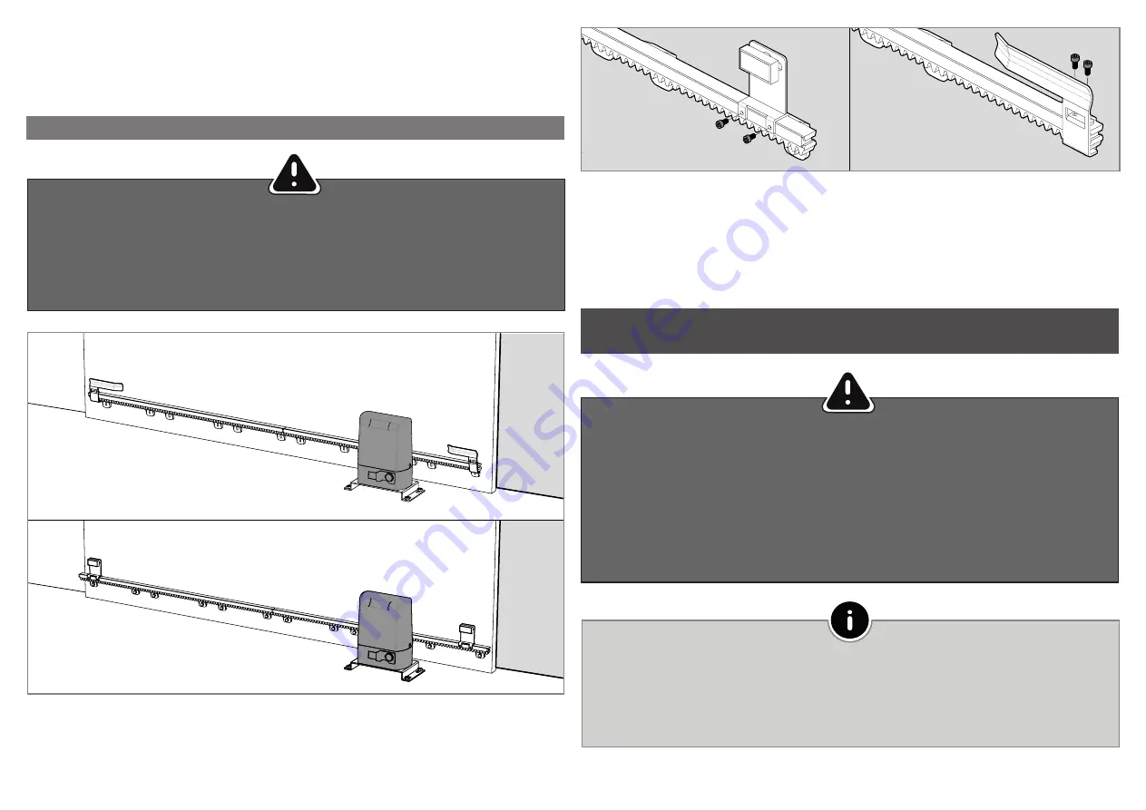
The magnetic limit switch activates when the
magnet is aligned with the motor reader.
•
The mechanical limit switch activates when the
plate tilts the motor spring.
2 • Insert the supplied DIN912 M5 x 12 screws into the accessories until the end plate is fully tightened to the rack.
3 • Move the gate to the closed position and repeat the previous steps to secure the locking limit stop plate.
8 • Repeat the previous steps for each meter of rack until you reach the end.
9 • Test the gate movement manually with all racks installed and weld the remaining spacers. If there is any
friction between the pinion and the rack, adjust the rack on the oval screws.
COMPONENTS TESTS
INSTALLATION OF PLATES THE LIMIT SWITCHES
Put the gate in the open position and unlock the engine!
The end-of-stroke must be in tune for the gate to stop before touching the closing or opening stops.
Test the drive with the door unlocked manually before connecting the motor to the electric current to avoid
problems due to poor configuration.
1 • Position the opening limit switch plate/magnet on the rack so that it is able to engage the limit switch on the
motor before the gate reaches the opening stop.
In order to detect if the fault is in the control panel or in the motor, it is sometimes necessary to perform
tests with a direct connection to a 230V power supply.
For this purpose, it is necessary to insert a capacitor into the connection so that the automation can opera-
te (check the type of condenser to be used in the product manual).
The diagram on the next page shows how this connection should be made and how to interleave the
different wires of the components.
All tests must be carried out by specialized technicians due to the serious danger related to the
misuse of electrical systems!
In order to carry out the tests you do not need to remove the operator from the place where it is installed,
because in this way you can see if the operator connected directly to the current can function correctly.
You must use a new capacitor during this test to ensure that the problem is not in the capacitor.


