background image

4

2

2

60

60

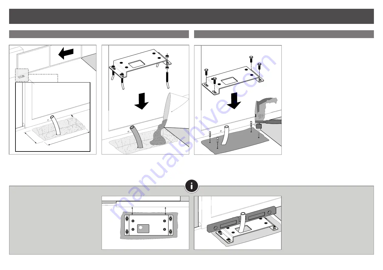
1 •  Drill a hole in the ground to create a concrete 
foundation.  

2 • Fasten the screws to the plate with females and 
females.

3 • Fill the hole with fresh concrete and smooth the 
top where you will secure the plate.

4 • Insert the plate with the screws in the fresh con-
crete base.


• 

In both cases you 

should leave pipes in the mi-

ddle of the hole for the passage of cables for power 
and accessories.

• The distance from the foundation to the gate must 
be 

at least 30mm. 

• The distance from the fixing plate to the gate 
should be 

60mm.


• 

Use a level


to level the foundation horizontally.

• Let the concrete dry so that the plate is firmly 
fixed.

CREATE FOUNDATION

REQUIRED ON ANY INSTALLATION

EXISTING FOUNDATION

530

30

0

30

1 •  Place the plate on top of the concrete base.

2 • Mark the location to drill bushings. Mark the center 
of the oval holes in the plate.

3 • Drill four holes for the M10 bushings in the concrete 
base. Place the M10 metal bushings in the holes.

4 • Place the plate on the concrete base with respect 
to distances. Tighten it with the M10 screws.

If there is already a foundation at the installation site, 
proceed as follows:

INSTALLATION

Summary of Contents for TOP500

Page 1: ...v1 0 REV 01 2019 TOP500 USER S AND INSTALLER S MANUAL ...

Page 2: ...in an emergency and provide him the manual This device can be used by children 8 year old or older and persons whose physical sensory or mental capa cities are reduced or by persons without experience or knowledge if they have received supervision or ins tructions on the use of the device in a safe manner and understood the hazards involved Children should not play with the device Cleaning and mai...

Page 3: ...imensions of the TOP500 operator are in milime ters mm throughout the manual 230V 110V Power Supply AC 230V 50Hz AC 110V 60Hz Power 280W 280W Current 0 8A 0 8A Speed 0 16 m sec 0 16 m sec Thermal protection 120ºC 120ºC Force 1200N 1200N Working temperature 25 C a 55 C 25 C a 55 C Capacitor 8µF 25µF IP IP44 IP44 Working frequency 25 25 Noise level LpA 56 dB A LpA 56 dB A Thermal reset 2min to compl...

Page 4: ... The distance from the fixing plate to the gate should be 60mm Use a level to level the foundation horizontally Let the concrete dry so that the plate is firmly fixed CREATE FOUNDATION REQUIRED ON ANY INSTALLATION EXISTING FOUNDATION 530 300 30 1 Place the plate on top of the concrete base 2 Mark the location to drill bushings Mark the center of the oval holes in the plate 3 Drill four holes for t...

Page 5: ...ock and turn the key to the original position Close the cover to finish perform a maneuver to confirm the operation of the operator 1 Position a piece of rack over the pinion level it horizontally with a level 2 Fasten the first rack bracket over the pinion to the gate 3 Close the gate slightly until the other end of the rack rests against the pinion and tighten the last bracket APPLICATION OF MOT...

Page 6: ... Open the gate until it rests against the tip of the new rack and over welds the spacer 7 Remove the auxiliary rack piece and open the gate until the pinion is over the other rack end Weld the spacer 4 Close the gate slightly by letting the rack rest against the pinion and apply another rack A by fitting it to the already screwed rack B 5 Open the gate until you rest the tip of the new rack piece ...

Page 7: ...or to the electric current to avoid problems due to poor configuration 1 Position the opening limit switch plate magnet on the rack so that it is able to engage the limit switch on the motor before the gate reaches the opening stop In order to detect if the fault is in the control panel or in the motor it is sometimes necessary to perform tests with a direct connection to a 230V power supply For t...

Page 8: ...inal inserting a capacitor into the opening and closing wires 3 After these connections are completed connect to a 230V outlet depending on the motor power unit being tested LUBRIFICATING COMPONENTS CHECK FRICTION BETWEEN RACK AND PINION CHECK DISTANCES AND TIPS 63 Make sure that the distance between rack and motor remains unchanged and that it engages the teeth of the motor pinion correctly over ...

Page 9: ...vices for diagnosis 1 Check capacitors testing with new capacitors 2 If capacitors are not the problem disconnect motor from control board and test it by connecting directly to power supply in order to find out if it is broken 3 f the motor doesn t work remove it from installation site and send to our technical services for diagnosis 4 If motor work well and move gate at full force during the enti...

Reviews: