11
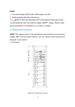
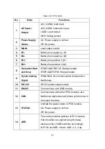
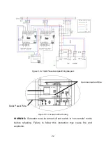
Table 4.4.3: PCS Parts
No.
Parts
Functions
1
AC Input /
Output
AC1 (GRID): Grid input.
AC2 (GEN): Generator input.
LOAD: Load output.
GND: Safety ground.
2
Power Supply
Status
On: Power supply is normal.
Off: No power.
3
MAIN
Load output switch.
4
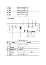
B1-
Battery bus negative (-)#1.
5
B2-
Battery bus negative (-)#2.
6
B1+
Battery bus positive (+)#1.
7
B2+
Battery bus positive (+)#2.
8
Generator Start
and Stop
START-A&START-B: Start generator.
STOP-A&STOP-B: Stop generator.
9
Synchronizing
Signal
SYN&GND, for communication between two
NetZeroes-
10
DC-12V
DC12V power supply output.
11
RS485
Communicate with EMS module.
12
CAN
Communicate with other PCS modules, two
NetZeroes applied as split phase synchronize in
the signal interface.
13
STATUS
Indicate the power status of PCS module:
On: Power supply is normal.
Off: No power.
14
ADD
The communication address of PCS module.
If two NetZero are applied as split phase,
please set the 4 ADD switches accordingly:
#1 PCS: set ADD 1 down, ADD 2, 3, 4 up;
Summary of Contents for iCAN NetZero
Page 1: ...iCAN NetZero User Manual Intelligent Energy System ICN1V1 0 4 ...
Page 2: ......
Page 35: ......


