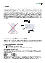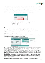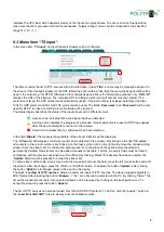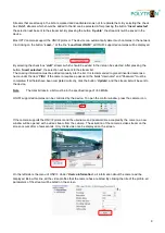
12
“
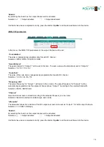
Symbol rate
“
The symbol rate must be set the same for both output channels and are
set via “Output 1”.
Selection: 1 - 7.2 MSps
“
Step
“
In this column, the bandwidth of the channel may
be set. This is determined via “Output 1“ for both output channels.
Selection: 6 MHz, 7 MHz, 8 MHz, 8.3 MHz
“
Frequency, kHz
“
The output frequency for “Output 1“ may be set in this column. The output frequency for “Output 2“ will be
automatically programmed as the adjacent channel above
“Output 1“ according to the selected bandwidth.
Selection: 45000 - 862000 kHz
“
Channel
“
Here, the channel name is stored according to the selected frequency or vice versa.
Selection: based on selected modulation type and country
“
Attenuator
“
The attenuator allows the reduction of the RF output level and can be set via “Output 1“ for both output channels.
Selection: 0 - 30 dB (1 dB steps)
“
Enable
“
By selecting the check box the output channel will be activated.
Selection:
= Output activated
= Output deactivated
If all fields have been completed correctly, press the button
“
Update
“ and the data will be sent to the device.
DVB-T RF parameters
In this menu the DVB-T RF parameters of the output channels will be set.
“
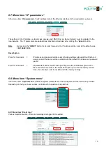
Constellation
“
The value is independently programmable for each RF channel.
Selection: QPSK, 16 QAM, 64 QAM
“
Bandwidth
“
In this item, the bandwidth of the channel will be se
t. This is determined via “Output 1“ for both output channels.
Selection: 7 MHz, 8 MHz
“
Guard interval
“
The guard interval is independently programmable for each RF channel.
Selection: 1/4, 1/8, 1/16, 1/32
“
Code Rate
“
The code rate is independently programmable for each RF channel.
Selection: 1/2, 2/3, 3/4, 5/6, 7/8
Summary of Contents for HDI 2 multi
Page 1: ...1 HDI 2 multi IP Modulator IP into DVB C DVB T ISDB T Manual 0902252 V1...
Page 22: ...22 Notes...
Page 23: ...23 Notes...


