background image


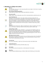
1. Mounting and Safety instructions 


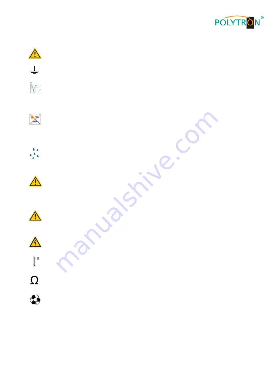
Attention 

The rated voltage on the device must be corresponding with the mains voltage. The instructions for operating 
the device must be observed.


Grounding and potential equalization 

Please establish grounding and perform potential equalization before initial startup.


Connection cable 

Always install the connection cables with a loop so that no condensed water can penetrate along the cable. 


Select installation site 

Install only on a solid, plane and at most fire-resistant surface. Avoid strong magnetic fields in the 
surroundings. Too strong heat effect or accumulation of heat will have an adverse effect on the durability. 
Don't mount directly over or nearby heating systems, open fire sources or the like, where the device is 
exposed to heat radiation or oil vapours. Don't block the ventilation slots of devices fitted with fans or 
heatsinks, as this will cause heat to build up inside the devices and may cause fire. Free air circulation is 
absolutely necessary to permit the device to function properly. IT's imperative to observe the mounting 
position! 


Moisture 

Protect the device from high humidity, dripping and splashing water. If there is condensation, wait until the 
device is completely dry. Operating environment according to the specified IP protection class.


Caution! Danger of life! 

According to the currently valid version of EN 60728-11, coaxial receiving and distribution systems must 
meet the safety requirements regarding grounding, potential equalization, etc., otherwise damage to the 
product, fire or other hazards may occur. Electrical fuses may only be replaced by authorised specialist 
persons. For the replacement of electric fuses, only same type and amperage have to be used. In case of 
damage the device has to be taken out of service.


Mounting and service works  

May be only done by authorized staff according to the rules of technology. Devices have to be switched off 
before starting any maintenance or service work. In order to guarantee interference immunity, all device 
covers must be screwed tight again after opening.


Thunderstorm  

Do not carry out maintenance or repair work on the device due to higher risk of lightning strike.


Ambient temperature 

Operation and storage only within the specified temperature range.


Termination 

Not used receiver and trunk line outputs have to be terminated with 75 Ohm resistors.


Recycling 

All of our packaging materials (packaging, identification sheets, plastic foil and bag) are fully recyclable.


Summary of Contents for HDI 2 multi

Page 1: ...1 HDI 2 multi IP Modulator IP into DVB C DVB T ISDB T Manual 0902252 V1...

Page 2: ..._________________________________________16 6 8 2 Menu item Change password ___________________________________________16 6 8 3 Menu item User management ___________________________________________17...

Page 3: ...dripping and splashing water If there is condensation wait until the device is completely dry Operating environment according to the specified IP protection class Caution Danger of life According to t...

Page 4: ...efined packing and transportation materials Damage caused by faulty connections and or improper handling are excluded from any liability Waste disposal Electronic equipment does not belong in househol...

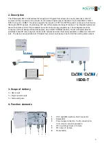
Page 5: ...easy programming The management and the connection of the IP transport stream takes place via an RJ45 100Mbit s interface The IP modulator offers the possibility to feed IP camera signals into the cab...

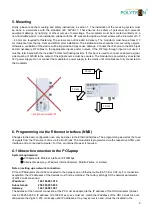
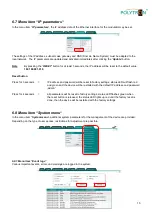
Page 6: ...connect the modulator s power supply to the mains until all cables are fully connected to the modulator 6 Programming via the Ethernet interface NMS Changes to the basic configuration can only be done...

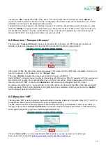
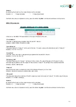
Page 7: ...device homepage will display the main information about the device and its status File tabs for programming the HDI 2 multi are available at the top of the window In the device description Device info...

Page 8: ...ndicates that no valid stream has been detected In the field Bitrate the measured input bitrate of the stream in Mbit s will be displayed The CC errors field displays continuity counter errors detecte...

Page 9: ...to give all inserted cameras a name under the item Title If the camera requires a password the fields Username and Password must be completed If all fields have been completed correctly click the but...

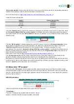
Page 10: ...ates the actual input bit rate of the service in Mbit s Under LCN v 1 a logical channel number can be assigned for the service If the TV supports LCN the services will be sorted by this number Zero me...

Page 11: ...activated If a different value is desired clear this check box and enter the value manually Normally the Original network ID is the same for all output channels throughout the network Exact values ca...

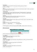
Page 12: ...the reduction of the RF output level and can be set via Output 1 for both output channels Selection 0 30 dB 1 dB steps Enable By selecting the check box the output channel will be activated Selection...

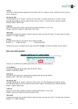
Page 13: ...vated If all fields have been completed correctly press the button Update and the data will be sent to the device DVB C Annex B RF parameters In this menu the DVB C Annex B RF parameters of the output...

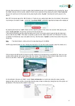
Page 14: ...ly programmable for each RF channel Selection 1 2 2 3 3 4 5 6 7 8 Frequency kHz The output frequency for Output 1 will be set in this column The output frequency for Output 2 will be automatically pro...

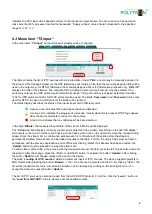
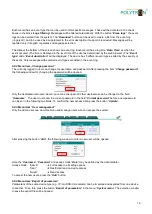
Page 15: ...password will be reset to factory settings status LED will flash red and green and the device will be restarted with the default IP address and password admin Press for 4 seconds all parameters will b...

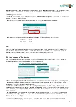
Page 16: ...can change his username and password After pressing the item Change password the following window for changing the password will be opened Only the dedicated username admin cannot be changed All other...

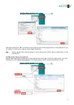
Page 17: ...n Note Use the exported file to import parameters only to another device with the same modulation type or to the same device 6 8 5 Menu item Import of parameters Exported parameters from one HDI 2 mul...

Page 18: ...which the file was exported Press the button Upload to send the parameters to the device The import of parameters from one software release to another is also allowed New parameters or parameters tha...

Page 19: ...s in process The login window will appear on the screen once the firmware upgrade is complete The browser does not need to be updated All device settings remain unchanged 6 8 7 Menu item Restart the d...

Page 20: ...ill be accepted 6 8 11 Menu item Date time In the menu item Date time in the tab System menu the user can specify the time source for the IP modulator Local time shows the time taking into account pos...

Page 21: ...2 2 3 3 4 5 6 7 8 Symbol rate 1 7 2 MSps 5 057 6 36 MSps FFT 2K MER 40 dB 35 dB 40 dB Number of channels 2 Channel allocation Adjacent channel Output level 90 dB V Attenuator 0 30 dB 1 dB steps Connec...

Page 22: ...22 Notes...

Page 23: ...23 Notes...

Page 24: ...hme H Q Order department 49 0 70 81 1702 0 Technische Hotline Technical hotline 49 0 70 81 1702 0 Telefax 49 0 70 81 1702 50 Internet http www polytron de Email info polytron de Technische nderungen v...

Reviews: