6
5. Mounting
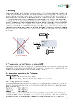
Firstly, please read the mounting and safety instructions in section 1. The installation of the receiving system must
be done in accordance with the standard
IEC 60728-11
. That ensures the safety of personnel and prevents
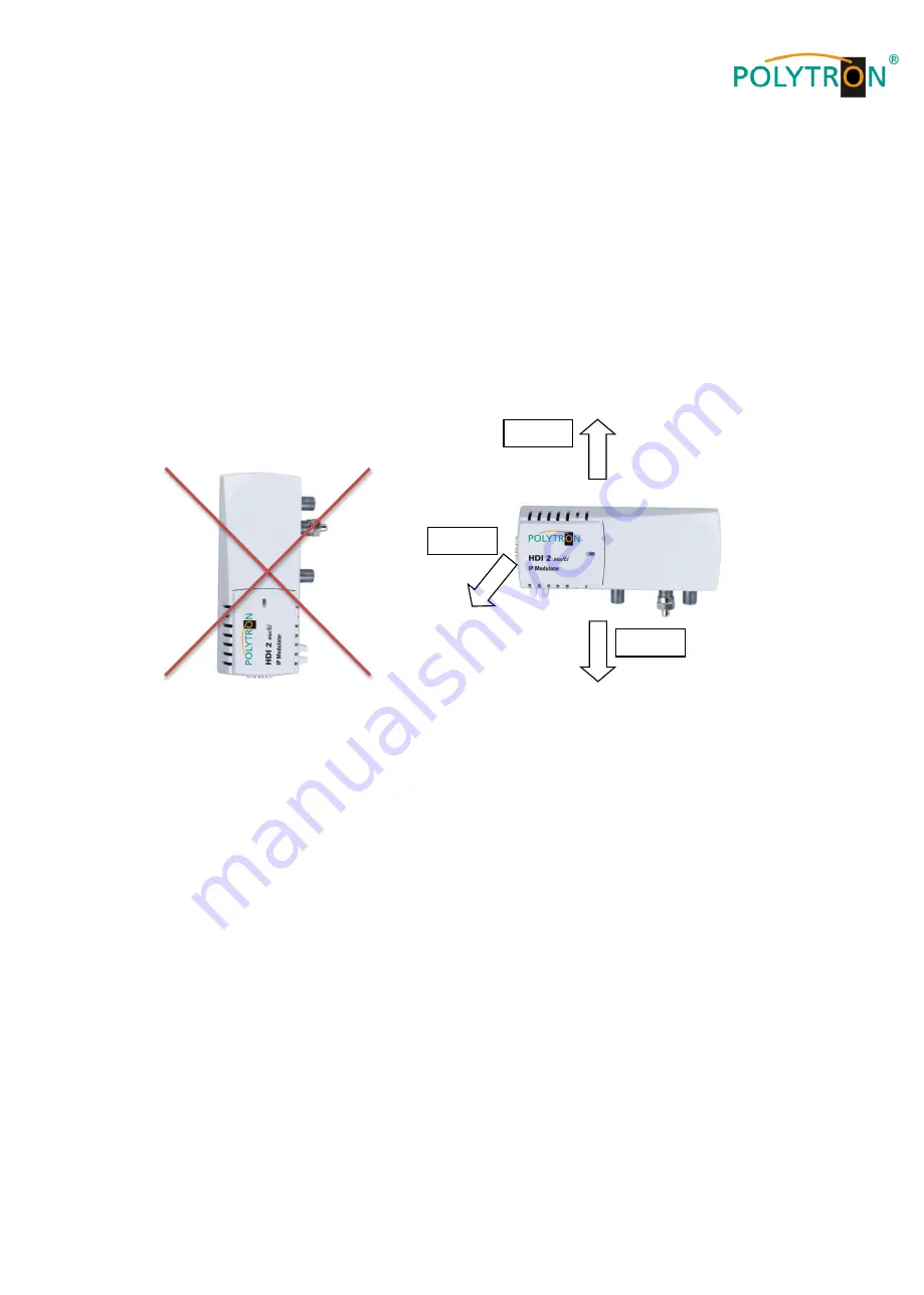
equipment damage by lightning or other sources of overvoltage. The modulator must be mounted vertically on a
non-flammable wall or in an installation cabinet with the RF sockets facing down. Steel screws with a diameter of 3.5
- 4.0 mm are required for fastening. The screws are not included in delivery. The modulator must have at least 10
cm clearance from the top, front and bottom after installation. The installation slots should be not covered by objects.
Otherwise, ventilation of the device will be impaired and may cause damage. Connect the IP source to the RJ45 jack
and all necessary RF cables to the appropriate inputs and/or outputs. If the RF loop-through input is not used, it
must be terminated with the included 75 Ohm terminating resistor. If this input is used to connect an antenna signal,
a decoupling of
≥20dB to the output of the signal source must be ensured. The modulator is powered by an external
12V power supply. Do not connect the modulator
’s power supply to the mains until all cables are fully connected to
the modulator.
6. Programming via the Ethernet interface (NMS)
Changes to the basic configuration can only be done via the Ethernet interface. The programming as well as the feed
of signals from the IP source is done via the RJ-45 jack. The modulator is programmed via the respective HTML user
interface and a connected computer. For this, an internet browser is required. .
6.1 Network connection to the PC/laptop
System requirements:
PC/laptop with Ethernet interface 10/100Mbps
Internet browser (e.g. Windows Internet Explorer, Mozilla Firefox, or similar)
Note on setting up a network connection:
PC and IP Modulator should be connected to the network via an Ethernet cable (CAT-5E or CAT-6). For connection
acquisition, the IP addresses of the devices must first be matched. The factory settings for the network parameters
of HDI 2 multi are shown:
IP address:
192.168.001.010
Subnet mask:
255.255.255.000
Gateway:
192.168.001.001
The address of the network connection at the PC must be adapted to the IP address of the HDI modulator (Subnet
mask: 255.255.255.0, IP address: 192.168.001.xxx). xxx must not match the IP address of the HDI 2 multi. Also not
allowed are the digits 0, 255 or already used IP addresses. If a proxy server is used, it must be disabled in the
10 cm
10 cm
= Heat accumulation!!!
10 cm
Summary of Contents for HDI 2 multi
Page 1: ...1 HDI 2 multi IP Modulator IP into DVB C DVB T ISDB T Manual 0902252 V1...
Page 22: ...22 Notes...
Page 23: ...23 Notes...


