


6
Pololu
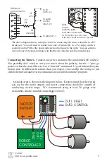
Connecting the Motor Controller
There are eight pins on the bottom of the motor
controller for connecting it to the rest of your system.
A closeup of the bottom of the PCB is shown to the
right, in case you have a hard time reading the
silkscreen on your board. The eight pin
labels and the corresponding functions are
shown in the table.
C o n n e c t i n g P o w e r .
W a r n i n g :
connecting power incorrectly can cause
some components to explode.
Connect
the ground pin to a ground terminal on
your robot controller. If you have a
separate power supply for just the motors,
make sure that you connect the negative
terminal of that supply to the same ground.
(This situation may arise if, for example, you want to run your robot controller off of a
9-volt battery and you want to run your motors off of a 12-volt battery. You will also
need an independent power supply for the motors if you want to use a personal
computer as the robot controller. In that case, you might use a battery for the motor
supply and use a wall outlet for the PC supply.) Connect the ‘+’ pin to the positive
terminal of the motor supply; this terminal may connect only to the motor controller, or
it may connect to any other device powered by that supply.
Warning
: the supply
voltage may not exceed 16 volts or 25 volts, depending on which capacitor you chose
for C1 in step 5 of assembly.
Reset Input.
The reset input is optional, but you
C
may need to use it to ensure that
spurious signals sent when your robot controller turns on do not cause the motor
controller to detect the baud rate incorrectly.
onnect this pin to a 0-5V digital output
on your robot controller. The line should normally be kept high (+5V), but bringing it
low (to 0V) for at least 2 microseconds resets the motor controller to its initial state (all
motors off, waiting for its first serial command).
Serial Input.
Use a pin on your robot controller that can be used as a TTL-level,
asynchronous serial output. Serial data can be sent down this line 8 bits at a time, with
no parity bit, at any rate between 1200 and 19200 baud.
Once you choose a baud rate,
you cannot change it until the motor controller is reset
.
Important note:
unlike
RS-232 serial lines (the standard for serial ports used to connect devices to personal
computers), this line uses TTL voltages (between 0 and 5 volts). The higher voltages
used on RS-232 lines will damage the motor controller. If you need to convert RS-232
levels to TTL levels, you will need to use a level converter such as the MAX220 (made
by Maxim). You could also use the simple circuit shown at the top of the next page.
When building circuits that connect to a PC, be especially careful because you
could potentially destroy the PC’s serial port. Before attempting to connect your
own electronics to a computer, make sure you know what you are doing!
LABEL
FUNCTION
-
+
1
2
M1+
M2-
M2-
M1-
ground (0V)
positive supply (5.6-25V)
reset
serial control input
motor 1, negative output
motor 2, positive output
motor 1, positive output
motor 2, negative output
© 2001
http://www.pololu.com/


