


3
Pololu
soldering iron
solder
PCB
good
bad
1: solder
2: check
3: trim leads
How to Solder
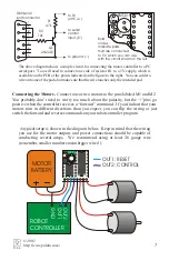
You need a soldering iron and diagonal cutters to assemble the motor controller. The
green printed circuit board (PCB) is the base that holds the components together and
establishes the necessary electrical connections. The PCB has two sides: a top side, or
component side
, which has white
silkscreen markings, and a bottom side,
or
solder side
. Insert the components
from the top side and solder them on the
solder side. In general, you should
insert and solder the components so that
they are as close as possible to the PCB.
All components in this kit, except for
voltage regulator U3, should be flush
with the PCB. After soldering, trim
excess leads with diagonal cutters.
To solder, heat a component lead and the
PCB pad and then apply solder until the
solder flows onto both the lead and the
pad. If the solder beads up on the lead or
on the pad, the connection is bad, so you
should apply more heat. However, be
careful not to damage any components
through overheating.
Contacting Pololu
You can check the Pololu web site at
http://www.pololu.com/
for latest
information about the motor controller, including color pictures, application examples,
and troubleshooting tips.
We would be delighted to hear from you about your project and about your experience
with our motor controller. You can contact us through our online feedback form or by
email at
. Tell us what we did well, what we could improve,
what you would like to see in the future, or anything else you would like to say!
top
bottom
© 2001
http://www.pololu.com/


