

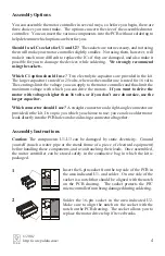


Next, solder in your choice of connector. You can use
either the straight or the right-angle female header
provided in your kit, or use your own connector. If you
prefer having leads soldered directly to the PCB, you
can do so now or wait until you have the leads ready and
available.
6
SMC01A
C
2
C
1
U3
U2
U1
M2
1 2
M1
Finally, insert the two integrated circuits (ICs), U1
and U2, into their sockets.
Make sure that you plug
them in so that the notches on the ICs match the
notches on the PCB outline. Do not solder the ICs
to the sockets.
If you soldered the sockets in
backwards, it doesn’t matter as long as the actual
component is oriented correctly.
Be careful: the ICs
are static-sensitive
, so take appropriate precautions
and avoid touching their leads. You may need to bend
some of the leads to make them fit in the sockets; if so,
hold the plastic body of the IC and push the pins
(gently!) against a flat surface, one row at a time.
7
SMC01A
C
2
C
1
U3
U2
U1
M2
1 2
M1
5
Pololu
SMC01A
C
2
C
1
U3
U2
U1
M2
1 2
M1
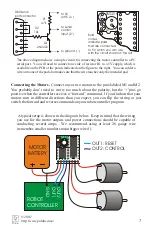
Next, add the tantalum capacitor C2. You may need to
bend the leads to make them straight so that they will
fit. The capacitor is
polarized
, which means it
must
only go in one way
. Make sure the side labeled with a
“+” and a stripe goes into the hole that is also marked
with a “+”. If the PCB is oriented as shown in the
diagram, the lower hole is for the positive lead.
3
+
SMC01A
C
2
C
1
U3
U2
U1
M2
1 2
M1
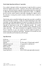
Now, add the voltage regulator, U3. Make sure the
device is oriented as shown on the silkscreen drawing,
with the flat side facing the outside of the PCB.
Caution! The voltage regulator can be damaged by
static electricity.
4
SMC01A
C
2
C
1
U3
U2
U1
M2
1 2
M1
In this step, add your choice of electrolytic capacitor for
C1. The larger capacitor is necessary if you want to run
your motors off of a 24-volt power source, and you
should use it if you don’t care about the size of the
completed motor controller.
The electrolytic
capacitors are polarized, but this time the stripe
identifies the negative terminal.
Also, the positive
lead is longer. Make sure to match up the positive lead
with the appropriate hole in the PCB.
5
+
+
© 2001
http://www.pololu.com/


