


Note that the kit includes two different sizes of #2-56 machine screws: 3/16″ and 1/4″. The two longer screws
are intended for use in the front holes (near the motors) so that the additional thickness of a sumo blade can be
accommodated. While you can add the blade before screwing the robot together for the first time, we suggest
waiting until after you have soldered in the 2×12 connector for the front sensor array so that you have more room
to work.
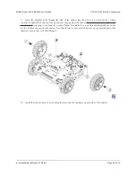
11. Solder each motor lead to the main board, then trim off the excess length of wire.
Pololu Zumo 32U4 Robot User’s Guide
© 2001–2015 Pololu Corporation
4. Assembling the Zumo 32U4 kit
Page 39 of 76