


4. Assembling the Zumo 32U4 kit
See
Section 1.1
for a diagram to help you identify the contents of the Zumo 32U4 robot kit.
Please follow these instructions carefully to assemble your Zumo 32U4 robot kit properly. If you have an
assembled version of the Zumo 32U4 robot, you can skip to
Section 5
and start programming it!
Main board additions
Most of the hardware on the Zumo 32U4 main board consists of surface-mount components that are already
soldered to the board, but there are a few through-hole parts that you need to solder yourself.
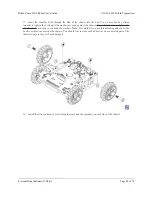
1. Solder the buzzer to the top of the main board, matching its orientation to the printed outline, then trim
the excess length from the buzzer leads underneath the board.
2. Solder the two 1×2 machine pin sockets to the top of the board in the front corners.
3.
Optional:
If you plan to connect headers or wires to the top expansion area, consider soldering them
now.
Pololu Zumo 32U4 Robot User’s Guide
© 2001–2015 Pololu Corporation
4. Assembling the Zumo 32U4 kit
Page 32 of 76