


While it is still possible to solder all of these parts after the main board has been mounted on the chassis,
soldering them beforehand is easier and avoids the risk of inadvertently melting the chassis with your soldering
iron.
Motors
If you have an older Zumo 32U4 kit with white sprockets (which we shipped before May 2015),
you should skip step 4 and install the drive sprockets after step 14 instead, at the same time as
the idler sprockets. (If the white drive sprockets were attached now, their shape would make the
motors, chassis, and main board difficult to assemble.)
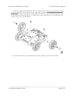
4. Press the output shafts of the motors into the drive sprockets, with the “teeth” of the sprockets facing
the motor. The end of the gearbox shaft should end up flush with the outside of the sprocket. A good way
to do this is to set the wheel on flat surface (like a table top) and press the motor shaft into the wheel until
it contacts the surface.
Pololu Zumo 32U4 Robot User’s Guide
© 2001–2015 Pololu Corporation
4. Assembling the Zumo 32U4 kit
Page 33 of 76